

The Role of Rigid-Flex PCBs in Aerospace & Defense Prototypes
.png?resizemode=force&maxsidesize=500)
What Are Rigid-Flex PCBs?
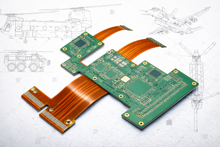
Rigid-flex PCBs combine rigid substrates and flexible circuits into a single, unified interconnect structure. Rigid sections provide mechanical support for component mounting, while flexible polyimide layers bend to connect different areas of the board.
Unlike traditional designs that rely on connectors and cables between boards, rigid-flex PCBs integrate everything into one stackup. Flex layers run continuously through rigid sections, eliminating discrete interconnects.
This architecture delivers both structural stability and routing flexibility, making rigid-flex PCBs ideal for Aerospace & Defense prototypes where packaging constraints and reliability requirements are tightly coupled.
Why Rigid-Flex PCBs Matter in Aerospace & Defense Prototypes
Rigid-flex PCBs are widely adopted in A&D prototypes because they solve multiple design challenges at once.
SWaP Optimization (Size, Weight, and Power)
Rigid-flex designs reduce or eliminate connectors, wiring harnesses, and mounting hardware. This leads to lighter, smaller assemblies, which is critical for airborne and space-constrained systems.
Improved Reliability in Harsh Environments
By removing connectors and solder joints between boards, rigid-flex PCBs reduce common failure points. The monolithic structure improves resistance to shock, vibration, and thermal cycling.
Better Electrical Performance
Shorter interconnect paths and fewer discontinuities improve signal integrity. This is especially important for high-speed digital, RF, and low-noise analog circuits used in defense electronics.
Advanced Packaging Capability
Rigid-flex enables true three-dimensional routing, allowing designs to conform to tight enclosures, fold around structures, and maximize usable space.
Materials and Construction Considerations
Material selection plays a major role in rigid-flex performance:
- Rigid sections: FR-4 or high-Tg laminates for structural stability
- Flex cores: Polyimide films for thermal and mechanical resilience
- Copper types: Rolled annealed copper for dynamic flexing; electro-deposited copper for static applications
- Coverlay: Used instead of solder mask to protect flex circuits
- Adhesiveless constructions: Improve reliability by reducing failure points
- Surface finishes: ENIG, ENEPIG, or hard gold depending on wear and assembly needs
Stiffeners and selective reinforcements may also be added to support components or connectors in flexible regions.
Key Design Considerations for Engineers
Rigid-flex PCB design requires careful planning across electrical, mechanical, and manufacturing domains.
Stackup and Layer Transitions
Define rigid and flex regions early. Maintain symmetry and controlled impedance across transitions. Use no-flow prepregs to manage bonding between rigid and flex layers.
Bend Radius and Flex Design
A common starting point is:
- Static bends: ~10x total flex thickness
- Dynamic bends: ~20x or more
Tighter bends increase the risk of copper cracking and dielectric failure.
Copper and Trace Design in Flex Areas
- Use curved traces instead of sharp angles
- Avoid routing perpendicular to bend lines
- Use hatched copper to maintain flexibility while preserving shielding
- Balance copper to reduce stress and warping
Component and Via Placement
- Keep components in rigid boards whenever possible
- Avoid vias in dynamic flex areas
- Add strain relief at rigid-to-flex transitions
Thermal and Mechanical Management
Account for thermal cycling, high-altitude conditions, and vibration. Use appropriate Tg materials, thermal vias, and heat spreading strategies where needed.
Relevant IPC and Aerospace Standards
Rigid-flex PCBs used in Aerospace & Defense prototypes must align with both IPC standards and program-specific requirements:
- IPC-2223 – Design standard for flexible and rigid-flex PCBs
- IPC-6013 – Qualification and performance specification (typically Class 3 for aerospace/defense)
- IPC-A-600 – Acceptability criteria for workmanship
- IPC-6012 – Applies to rigid sections within the design
- J-STD-001 Class 3 – High-reliability soldering requirements
Additional aerospace and defense requirements may include:
- AS9100 – Quality management systems
- ITAR / EAR – Export control compliance
Early alignment with these standards reduces redesign cycles and supports faster qualification.
Applications in Aerospace & Defense Prototypes
Rigid-flex PCBs are commonly used in:
- Avionics systems: Flight controls, navigation, and cockpit electronics
- RF and communications modules: Radar, secure communications, and signal processing
- Unmanned systems (UAVs): Lightweight, compact electronics for flight control and payloads
- Satellite and space electronics: High-reliability interconnects in constrained environments
- Military wearable systems: Rugged, compact electronics for field use
In each case, rigid-flex PCBs enable engineers to validate both electrical and mechanical performance in a single prototype build.
Prototype and Qualification Best Practices
To successfully deploy rigid-flex PCBs in Aerospace & Defense prototypes:
- Engage your fabrication partner early in the design phase
- Co-develop stackups, impedance targets, and bend requirements
- Include test coupons for impedance and reliability validation
- Perform bend-cycle, vibration, and thermal testing
- Validate signal integrity and power integrity during bring-up
- Maintain detailed documentation including stackups, bend diagrams, and material traceability
Treat the rigid-flex PCB as a complete system rather than separate rigid and flex elements.
Cost and Lead Time Considerations
Rigid-flex PCBs typically have higher upfront costs and longer lead times due to:
- Complex lamination processes
- Specialized materials
- Additional engineering requirements
However, total system cost is often reduced through:
- Fewer connectors and cables
- Simplified assembly
- Improved long-term reliability
Conclusion
Early DFM engagement is key to optimizing both cost and schedule.
Rigid-flex PCBs play a central role in Aerospace & Defense prototypes by enabling compact, lightweight, and highly reliable electronic systems. Their ability to combine structural support with flexible interconnects makes them uniquely suited for mission-critical applications.
For design engineers, success depends on understanding materials, bend mechanics, stackup design, and compliance requirements such as IPC-2223 and IPC-6013. By collaborating early with an experienced manufacturing partner and validating both electrical and mechanical performance, teams can accelerate development while meeting the stringent demands of Aerospace & Defense programs.
Related Posts

5 Reasons ‘Working’ Schematics Fail During PCB Layout

What Is MIL-PRF-31032?
