


5 PCB Failures That Ground Drones, and How to Design Against Them

In our experience manufacturing PCBs for commercial, industrial, aerospace, and defense UAV programs, many drone failures can be traced back to the same five board-level problems.This article explains the five most common PCB failure modes we see in drone electronics, what causes them, and the design and manufacturing practices that reduce risk before production begins.
Failure 1: Solder Joint Fatigue from Sustained Vibration
What it looks like:
- Intermittent system resets during flight
- Sensors dropping off communication buses
- ESC instability at specific throttle ranges
- Flight controllers that pass bench testing but fail after repeated flight cycles
These failures are often difficult to reproduce consistently and are commonly mistaken for software or firmware problems.
 What’s actually happening:
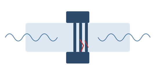
Drone motors generate continuous vibration across a broad frequency spectrum, often ranging from approximately 10 Hz to several kilohertz depending on motor speed, propeller balance, frame resonance, and payload configuration. Over time, solder joints fatigue, particularly on large, heavy components like BGAs, power connectors, shielded RF modules and heavy through-hole components. The damage accumulates gradually until microcracks form within the solder joint. This creates intermittent electrical connections that become increasingly unstable under vibration and temperature changes.
How to design against it:
- Use high-reliability assembly processes. For mission-critical UAV electronics, assemblies are often built to IPC-A-610 Class 3 and J-STD-001 Class 3.
- Consider underfill on critical BGAs. Underfill epoxy beneath BGA packages helps distribute mechanical stress across the package rather than concentrating it on individual solder balls. This can significantly improve vibration resistance on flight controllers, AI processors, and navigation systems.
- Mechanically secure large components. Heavy components should not rely solely on solder joints for mechanical retention. Adhesive staking or mechanical reinforcement is commonly used for connectors, large electrolytic capacitors, inductors and tall components exposed to vibration
- Increase PCB stiffness strategically. Increasing board rigidity can help move resonant frequencies away from dominant motor vibration ranges. This may include:
- Increased board thickness
- Additional copper planes
- Stiffeners
- Optimized mounting locations
- Improved mounting hole support
- Validate with vibration testing. Drone electronics should be validated using vibration profiles representative of the actual operating environment. Random vibration testing is often more representative of UAV flight conditions than simple sinusoidal testing alone.
Failure 2: Thermal Failure on ESC and Power Distribution Boards
What it looks like:
- ESC shutdowns during aggressive maneuvers
- Thermal hot spots on power boards
- Brownouts under peak load
- Delamination near MOSFETs or power stages
- Reduced flight time due to thermal throttling
 What’s actually happening:
Motor controllers in performance drones can draw over 100 amps during aggressive throttle inputs. That current has to flow through copper traces, and if those traces are undersized, or if the thermal dissipation path out of the board is inadequate, heat accumulates faster than it can escape. The board operates fine at moderate throttle and fails exactly when the pilot demands maximum performance.
This is almost always a design problem, not a manufacturing problem. But it's a design problem that a good manufacturing partner should catch before it reaches production.
How to design against it:
- Use IPC-2152 for conductor sizing. Many older calculators reference IPC-2221 charts, but IPC-2152 is the more appropriate modern standard for conductor current-carrying capacity and thermal rise calculations.Drone power systems should be designed around:
- Peak current loads
- Thermal rise limits
- Ambient operating temperature
- Copper thickness
- Plane geometry
- Airflow conditions
- Use heavier copper where required. While 1 oz copper is common on signal layers, drone power sections frequently require require 2 oz copper, and high-performance applications may warrant 3–4 oz. Heavier copper not only improves current handling but also improves heat spreading across the PCB.
- Design effective thermal via arrays. MOSFETs and QFN packages dissipate heat primarily through exposed thermal pads. Thermal via arrays beneath these devices help transfer heat into internal and backside copper planes. Without adequate thermal vias, localized temperatures rise rapidly and reduce long-term reliability.
- Select laminate materials carefully. Standard FR-4 may not provide sufficient thermal performance for high-power UAV electronics, Designers should evaluate characteristics such as Tg (glass transition temperature), Td (decomposition temperature), Z-axis expansion, thermal conductivity, and more.
- Run thermal simulation early. Thermal modeling during layout can identify hot spots, uneven current distribution, thermal bottlenecks, and e
- Excessive component junction temperatures. Catching thermal issues before fabrication is substantially less expensive than redesigning after testing.
 Failure 3: RF Interference Disrupting GPS, Telemetry, and Control Links
What it looks like:
- GPS instability
- Reduced control range
- Telemetry dropouts
- Navigation errors
- RF desense during throttle changes
- Intermittent communication failures
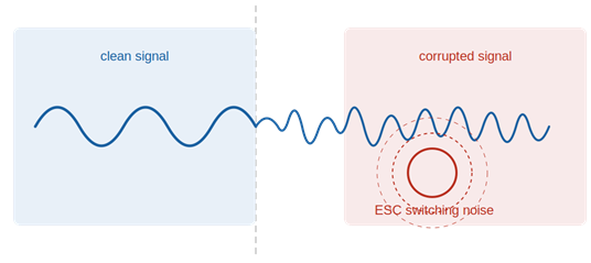
Drones are a uniquely hostile RF environment. You have high-current switching circuits generating broadband noise right next to the sensitive RF receivers that the drone's navigation and control systems depend on. Poor PCB layout allows that noise to couple into the RF chain through three mechanisms: conducted interference on shared power planes, radiated EMI from noisy traces acting as antennas, and ground plane disruptions that destroy the impedance control of RF signal paths.
This is one of the most common issues we see on boards submitted for DFM review, and it's almost always a layout problem rather than a component selection problem.
How to design against it:
- Separate RF and power domains. RF circuitry should be isolated from noisy switching power circuits as much as layout constraints allow. There is no universal spacing rule because acceptable separation depends on power levels, frequencies, shielding, and stack-up configuration. Design strategies include:
- Physical separation
- Shielding structures
- Dedicated RF ground regions
- Careful return path control
- Layer isolation
- Maintain uninterrupted reference planes. One of the most common RF layout failures is splitting the reference plane beneath RF traces.Controlled impedance routing requires a continuous return path beneath the signal trace. Plane interruptions increase impedance discontinuities and radiated emissions.
- Maintain controlled impedance routing. GPS, telemetry, and antenna traces are transmission lines that typically require controlled impedance, commonly 50 ohms. Impedance control depends on trace geometry, copper thickness, dielectric constant, distance to reference plane and stack-up construction.
- Filter noisy power rails. Ferrite beads, LC filters, and proper decoupling help prevent switching noise from propagating into sensitive RF circuitry. Filtering is significantly easier to implement during layout than after prototypes fail EMC testing.
- Specify impedance requirements clearly. Controlled impedance requirements should appear explicitly in fabrication documentation.Without clear fabrication requirements, impedance consistency cannot be guaranteed.
Failure 4: Delamination and Via Cracking from Thermal Cycling
What it looks like:
- Boards failing only at temperature extremes
- Intermittent cold-start issues
- Via barrel cracking
- Layer separation
- Warpage
- Cracked solder joints after environmental testing
 What’s actually happening:
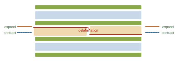
A drone operating at altitude experiences wide temperature swings from cold soak on the ground in winter conditions to self-heating during flight to cold ambient at altitude. PCBs are made of multiple materials with different coefficients of thermal expansion (CTE). When temperature changes, the copper, laminate, and solder all expand and contract at different rates. In a well-designed board, this is managed. In a poorly specified one, the mismatch stress accumulates in vias, traces, and solder joints until something cracks.
How to design against it:
- Use high-Tg materials for demanding environments. High-Tg laminates provide improved thermal stability and reduced mechanical degradation under elevated temperatures. This is especially important for sealed drone enclosures, high-current systems, outdoor operation, and aerospace UAV applications.
- Optimize via structures. Via reliability is critical in thermally demanding designs.Depending on the application, designers may consider filled vias, capped vias, via-in-pad structures, staggered microvias, and/or stacked microvias. The appropriate structure depends on current density, thermal stress, density requirements, and manufacturing capability.
- Maintain stack-up symmetry. Asymmetrical stack-ups increase the risk of warpage during fabrication and thermal cycling. Balanced stack-ups help reduce mechanical stress across the board structure.
- Validate through environmental testing. Drone electronics intended for harsh environments should undergo environmental validation testing.
Failure 5: Design-to-Production Misalignment
What it looks like:
- Prototypes work but production yield drops
- Reliability degrades during scaling
- Unexpected assembly variation
- Increased field failures between prototype and production
- Inconsistent electrical performance across builds
 What’s actually happening:
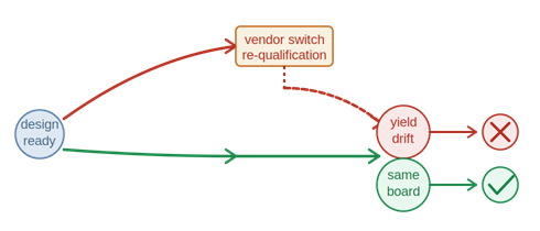
This failure mode is often operational rather than visibly electrical. When prototypes and production are built using different fabrication processes, material systems, or assembly methods, subtle process variation accumulates. Even suppliers claiming IPC compliance may produce significantly different process outcomes. For drone electronics operating near thermal, mechanical, or RF limits, these differences matter.
How to design against it:
- Use the same supplier from prototype through production. Using the same manufacturing partner through the entire product lifecycle reduces process variation and preserves manufacturing consistency.
- Request process documentation early. High-reliability suppliers should be able to provide:
- Reflow profiles
- Material certifications
- Impedance data
- Inspection reports
- Process documentation
- Traceability information
- Require traceability. Full material and batch traceability means that when a field failure occurs, you can trace it to a specific production lot within hours rather than weeks. For many programs, this isn't optional.
- Perform DFM review before fabrication. Design for manufacturability (DFM) review catches the stack-up decisions, trace widths, via specifications, and component placements that cause production problems before any boards are built. Correcting these issues before fabrication saves significant cost and schedule risk later. Try our FreeDFM tool here >
Conclusion
Across all five failure modes, the pattern is consistent: most drone PCB reliability problems are preventable when design engineering, material selection, stack-up planning, and manufacturing engineering are aligned early in the process.
Reliable UAV electronics require more than simply fabricating a board. They require a manufacturing partner that understands:
- Vibration reliability
- Thermal management
- RF layout constraints
- Controlled impedance
- High-current power delivery
- Environmental qualification
- Production scalability
At AdvancedPCB, we review every drone and UAV PCB design through our free DFM file check process before fabrication begins. Our team supports commercial, industrial, aerospace, and defense UAV programs with experience in:
- Power distribution
- RF and microwave
- High-current
- Thermal management
- Rigid and rigid-flex
We support IPC Class 3 manufacturing requirements, AS9100 quality systems, controlled impedance fabrication, AOI inspection, X-ray inspection, and full electrical test for high-reliability applications. View our certifications >
If you'd like to talk through your specific program, get in touch with our team.