


PCB Laminates
Selecting the right PCB laminate material is critical to signal integrity, thermal performance, manufacturability, and long-term reliability.
At AdvancedPCB, we help engineers choose PCB laminate materials for industrial, medical, aerospace, RF, and high-speed digital applications. From standard FR-4 to advanced low-loss materials, we support stack-up planning, impedance control, and thermal management to help ensure reliable performance from prototype through production.
Why PCB Laminate Materials Matter
PCB laminate materials form the structural and electrical foundation of a printed circuit board. In multilayer PCBs, laminates act as rigid cores while prepregs bond layers together during lamination. Material selection directly affects:
- Signal integrity and insertion loss
- Controlled impedance performance
- Thermal cycling reliability
- Mechanical stability and durability
- HDI and microvia reliability
- Manufacturability and fabrication yield
Choosing the right copper clad laminate PCB materials early helps reduce design risk and improve long-term reliability.
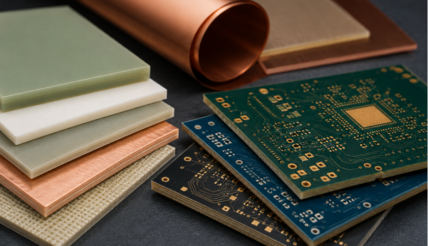
Common PCB Laminate Material Types
| FR-4 | Speed & Low-Loss | RF & Microwave | Flex & Rigid-Flex |
|---|---|---|---|
FR-4 remains the most common PCB laminate material for commercial, industrial, and general-purpose electronics. Modern FR-4 systems are available in standard, high-Tg, and low-loss variants to support a wide range of performance requirements. Benefits include:
| High-speed digital applications require laminate systems engineered for lower insertion loss and improved impedance consistency. These materials support:
Low-loss materials are optimized for stable Dk/Df performance and improved signal integrity. | RF applications often require PTFE-based or ceramic-filled laminate systems designed for:
These materials are commonly used in radar, antennas, aerospace electronics, and microwave communications. | Flex and rigid-flex PCB laminate materials use polyimide films and specialized copper foils to support compact and dynamic designs. Applications include:
|
Laminate Material Properties
Selecting the right laminate for your PCBs is an important part of the design process. The laminate will help achieve final thickness and give you a PCB that you can use for your application. At AdvancedPCB, all standard PCBs use FR4 laminate material.
| Laminate | Type | Tg Celsius | Td Celsius | T-260 Minutes | T-288 Minutes | Dk | Df | UL 94 |
|---|---|---|---|---|---|---|---|---|
Aluminum Clad | @ 1 MHz | @ 1 MHz | ||||||
130 | 380 | 4.8 | 0.016 | V0 | ||||
Isola | @ 1 GHz | @ 1 GHz | ||||||
FR4 / Phenolic | 180 | 340 | 60 | 30 | 4.04 @ 2 GHz | 0.021 @ 2 GHz | V0 | |
FR4 / Phenolic | 180 | 340 | 60 | >15 | 4.01 @ 2 GHz | 0.0200 @ 2 GHz | V0 | |
FR4 | 135 | 10 | 4.34 | 0.016 | V0 | |||
FR4 High Temp | 170 | 300 | 10 | >2 | 3.95 | 0.0161 | V0 | |
FR4 | 190 | 360 | 60 | >30 | 3.69 | 0.0091 | V0 | |
Modified Epoxy | 225 | 364 | 60 | >20 | 3.58 | 0.0059 | V0 | |
Polyimide | 260 | 416 | 60 | 60 | 3.78 | 0.0172 | HB | |
Polyimide | 260 | 396 | 60 | 60 | 3.78 | 0.0172 | V0 | |
Nelco | 1 GHz | 2.5 GHz | ||||||
FR4 High Temp | 175 | 325 | 4-8 | 4.0 @ 2.5 GHz | 0.022 | V0 | ||
Modified Epoxy | 175 | 345 | 30 | 4.1 | 0.02 | V0 | ||
N4000-12 | Modified Epoxy | 190 | 350 | >60 | 3.7 | 0.008 | V0 | |
N4000-13 | Modified Epoxy | 210 - 240 | 350 | >30 | >10 | 3.7 | 0.009 | V0 |
N4000-6 SI/EP | Modified Epoxy | 210 - 240 | 350 | >30 | >10 | 3.7 | 0.009 | V0 |
N4000-29 | FR4 High Temp | 175 - 185 | 350 | >60 | 15 | 4.3 | 0.015 | V0 |
Arlon | 175 | 1 MHz | 1 MHz | |||||
Cer/Glass | 250 | 407 | >60 | >60 | 4.2 | 0.01 | HB | |
Rogers | 8-40 GHz | 10 GHz | ||||||
PTFE / Glass | 500 | 2.2 | 0.0009 | V0 | ||||
PTFE / Microfiber | 500 | 2.33 | 0.0012 | V0 | ||||
Cer/PTFE | 500 | 2.94 | 0.0012 | V0 | ||||
Cer/PTFE | 500 | 6.45 | 0.0027 @ 10 GHz/A | V0 | ||||
Cer/PTFE | 500 | 10.7 | 0.0023 @ 10 GHz/A | V0 | ||||
Cer/PTFE | 500 | 3 | 0.001 | V0 | ||||
Cer/PTFE | 500 | 6.5 | 0.002 | V0 | ||||
Cer/PTFE | 500 | 11.2 | 0.0022 | V0 | ||||
Cer/PTFE | 500 | 3.02 | 0.0016 | V0 | ||||
Cer/PTFE | 500 | 10.8 | 0.0027 | V0 | ||||
Hydrocarbon/Cer | >280 | 425 | 3.55 | 0.0027 | N/A | |||
Hydrocarbon/Cer | >280 | 390 | 3.66 | 0.0037 | V0 | |||
Hydrocarbon/Cer | >280 | 390 | 3.3 ± 0.05 @ 10 GHz | 0.004 | V0 | |||
Taconic | 10 GHz | 10 GHz | ||||||
PTFE / Glass | 3.2 | 0.003 | V0 | |||||
PTFE / Glass | 2.95 | 0.0028 | V0 | |||||
PTFE / Glass | 2.5 @ 1 MHz | 0.0006 @ 1 MHz | V0 | |||||
PTFE / Glass | 553 | 2.55 | 0.0012 @ 1.9 GHz | V0 |
Flex and Rigid-Flex Laminate Materials
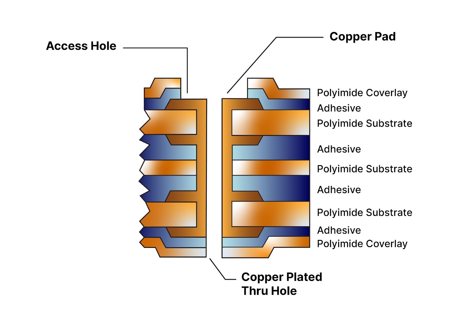
Polyimide films are the go-to choice for flex and rigid-flex board topologies, which, as shown in Figure 3, will include:
- Covercoat or coverlay
- Copper-clad material used as the base material
- Bond ply and adhesive (or prepreg)
- Rigid laminates
Both the coverlay and bond ply material use a polyimide film that buffers the board while also flexing with the board itself, while the adhesive layer secures itself to the copper traces. The thermal stability of the polyimide substrate encourages both stability and trace protection through the entire PCB stackup, regardless of flexure. Below is a cross-section diagram of a type 3 flex board.
Reliability and Manufacturability Considerations for PCB Materials
PCB reliability depends heavily on material selection, via structures, thermal expansion characteristics, and fabrication process compatibility.
AdvancedPCB helps engineers evaluate:
- High-Tg and low-CTE materials
- HDI and microvia compatibility
- Sequential lamination requirements
- Moisture absorption risks
- Thermal stress performance
Early collaboration between engineering and fabrication teams helps reduce risk before layout release and production.
Why Choose AdvancedPCB for PCB Laminate Expertise?
AdvancedPCB supports engineers with:
- Stack-up and laminate selection guidance
- Controlled impedance planning
- High-speed and RF material recommendations
- HDI and rigid-flex compatibility support
- Prototype and production fabrication
- U.S.-based engineering and manufacturing support
By aligning material selection with fabrication capabilities early, we help improve manufacturability, reduce delays, and support long-term reliability.
Stackup FAQs