


Drone PCBs: Requirements, Materials, Standards, and Design Priorities
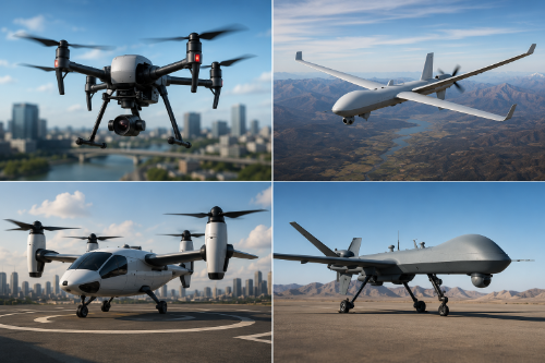
Whether designing electronics for commercial inspection drones, defense UAVs, delivery platforms, or eVTOL aircraft, PCB reliability directly impacts flight safety, mission success, and operational lifespan.
This guide explains the requirements that make drone PCBs different from conventional electronics, the materials and technologies commonly used in UAV applications, the IPC standards engineers should understand, and the design priorities that help prevent failures in the field.
Drone PCBs must withstand constant vibration, temperature extremes, high-current power delivery, RF interference, moisture exposure, and repeated flight cycles while remaining as lightweight as possible. These competing requirements drive unique design, manufacturing, and testing considerations throughout the product lifecycle.
What Makes a PCB Suitable for Drone Applications?
A drone PCB is designed and manufactured to operate reliably in an environment that combines mechanical stress, power density, and wireless communication challenges.
Unlike consumer electronics that remain stationary, drone electronics are subjected to:
- Continuous vibration from motors and propellers
- Repeated shock loads during takeoff and landing
- Rapid current fluctuations from ESCs and motors
- Exposure to moisture, dust, and temperature swings
- GPS, telemetry, and RF communication requirements
- Weight and space constraints
Successful drone PCB designs prioritize reliability without sacrificing weight, size, or performance.
Why Are Drone PCB Requirements More Demanding Than Traditional Electronics?
Many UAV failures can be traced back to PCB-related issues rather than software or mechanical components. Design engineers must manage:
- Power Density. Motor controllers can generate significant current spikes during acceleration and maneuvering. PCB copper thickness, plane design, and thermal management become critical.
- Vibration. Propeller and motor vibrations can fatigue solder joints, connectors, and heavy components over time.
- RF Performance. GPS, telemetry, video transmission, and control links are highly sensitive to EMI generated by switching power electronics.
- Environmental Exposure. Many drones operate in rain, humidity, salt air, dust, and temperature extremes.
- Weight Constraints. Every gram added to the PCB reduces payload capacity or flight endurance.
Which Design Priorities Matter Most for Drone PCBs?
Power Delivery Network Design
Reliable power distribution is one of the most important aspects of drone electronics. Designers should focus on:
- Low-impedance power planes
- Proper copper weight selection
- Bulk and local decoupling capacitors
- Thermal management around ESCs
- Short, high-current current paths
- Voltage drop reduction
Many high-power UAV applications utilize 2 oz copper or greater in power sections to improve current carrying capacity and heat spreading. IPC-2152 provides guidance for current-carrying conductor design.
RF and Signal Integrity
GPS receivers, telemetry systems, radar modules, and video transmission systems all depend on controlled RF performance. Key considerations include:
- 50Ω controlled impedance routing
- Continuous reference planes
- Separation between RF and power circuitry
- Proper antenna placement
- EMI mitigation techniques
- Differential pair routing where required
Poor PCB layout is one of the most common causes of GPS instability and telemetry dropouts in UAV systems.
Thermal Management
Unlike space systems where vacuum eliminates convection, drones rely on airflow and conductive heat transfer to control temperatures. Common thermal management techniques include:
- Heavy copper planes
- Thermal vias
- Heat spreaders
- High-Tg materials
- Strategic component placement
- Thermal simulation during design
ESCs, power converters, processors, and AI edge computing modules often represent the largest heat sources in modern UAVs.
Vibration Resistance
Motor vibration remains one of the leading causes of long-term PCB failures in drone applications.
Designers should consider:
- Underfill on critical BGAs
- Mechanical staking of large components
- Vibration-resistant connectors
- PCB stiffeners
- Symmetrical stackups
- Shock and vibration testing
Many aerospace and defense UAV programs validate electronics using vibration profiles representative of actual flight conditions.
Which PCB Materials Are Commonly Used in Drone Designs?
Material selection depends on the mission profile and performance requirements.
| Standard and High Tg FR-4 | High-Speed and RF Materials | Polyimide Flex & Rigid-Flex Materials |
|---|---|---|
|
The most common material for commercial UAVs. Advantages:
|
Common materials include:
These materials offer lower dielectric loss andimproved signal integrity at higher frequencies. |
Applications:
Benefits include:
|
Testing and Qualification for Drone Electronics
Drone PCBs should be validated beyond standard electrical testing. Typical qualification activities include:
- Thermal cycling
- Random vibration testing
- Shock testing
- Humidity testing
- Salt fog testing
- RF validation
- Power load testing
- Flight testing
Testing should replicate actual operating conditions whenever possible.
Conclusion
Successful drone PCB design requires balancing reliability, weight, power density, thermal performance, and RF integrity within a highly constrained environment. The most reliable UAV electronics are built on disciplined design practices, appropriate material selection, rigorous testing, and manufacturing processes capable of supporting both prototypes and production.
Whether you're developing a commercial drone, defense UAV, autonomous inspection platform, or next-generation eVTOL system, addressing these requirements early in the design process can significantly reduce development risk, improve flight reliability, and accelerate the path from prototype to deployment.