


Medical Rigid-Flex PCBs

For medical devices, the primary advantages are space savings, fewer connectors and cables, reduced assembly complexity, and the abilit yto fit electroincs into compact or irregular enclosures. Reliability, however, depends heavily on the rigid-flex stackup, materials, bend geometry, copper routing, transition areas, and manufacturing controls.
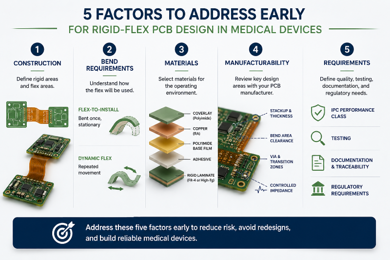
For engineers evaluating rigid-flex for a medical device, five factors should be addressed early:
- Construction: Determine where the PCB needs rigidity and where it needs to bend or fold.
- Bend requirements: Distinguish between flex-to-install and dynamic flex applications.
- Materials: Select polyimide, copper, adhesives, coverlay, and rigid laminates for the actual operating environment.
- Manufacturability: Review stackup, bend areas, vias, transition zones, and controlled impedance with the PCB manufacturer before layout is complete.
- Requirements: Define the applicable IPC performance class, testing, documentation, traceability, and product-specific regulatory requirements.
Early decisions in these areas can prevent expensive redesigns later.
What Is a Medical Rigid-Flex PCB?
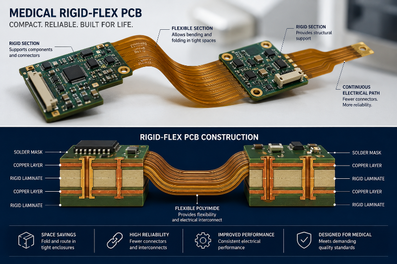
A medical rigid-flex PCB combines rigid PCB sections with flexible circuit sections in one integrated structure. The rigid sections provide mechanical support for components, connectors, and other devices. Flexible polyimide sections allow different areas of the circuit to bend, fold, or move relative to one another.
Unlike an assembly using separate rigid PCBs connected by cables or connectors, rigid-flex construction can create continuous electrical connections between rigid sections. This can reduce the number of interconnects and simplify packaging.
Common applications include:
- Wearable monitoring devices
- Diagnostic equipment
- Portable medical electronics
- Surgical instruments
- Imaging systems
- Drug-delivery equipment
- Other space-constrained medical electronics
Whether rigid-flex is appropriate depends on the electrical, mechanical, environmental, reliability, and regulatory requirements of the finished product.
Why Use Rigid-Flex PCBs in Medical Devices?
The strongest reason to use rigid-flex is often packaging efficiency. A flex section can fold around mechanical features or connect PCB sections positioned on different planes. That gives mechanical engineers more freedom when electronics must fit inside a small enclosure.
Rigid-flex can also eliminate some connectors, cables, and soldered interconnects. Fewer discrete connections can reduce assembly complexity and remove potential failure points. This is particularly useful in devices where size, weight, and reliability are important.
However, rigid-flex should not automatically be considered more reliable than a rigid-board solution. Reliability depends on whether the flex circuit is designed and manufactured for its actual mechanical environment. A circuit that bends once during installation has very different requirements from one that flexes thousands or millions of times during operation.
Materials Used in Medical Rigid-Flex PCBs
Rigid-flex construction combines materials with very different mechanical characteristics.
Polyimide
Polyimide is the most common dielectric material in flexible PCB sections because it provides good flexibility, thermal resistance, and dimensional stability. Both adhesive-based and adhesiveless flex constructions are available. Adhesiveless constructions can provide a thinner flex section and may offer advantages for applications requiring tighter bends, improved dimensional stability, or higher-temperature performance.
Copper
Flex circuits commonly use rolled annelated (RA) copper where repeated bending or flex fatigue is a concern because its grain structure is generally better suited to dynamic flexing than conventional electrodeposited copper.
Copper thickness also matters. Thinner copper generally improves flexibility, while heavier copper may be needed for higher-current circuits. The appropriate choice depends on both electrical and mechanical requirements.
Rigid Materials
Rigid portions commonly use FR-4 or other rigid laminate systems selected for the required thermal, electrical, and mechanical properties. Do not select material based on Tg alone. The complete material system should be evaluated for the intended environment, assembly process, electrical requirements, and reliability expectations.
Coverlay
Flexible sections commonly use polyimide coverlay to insulate and protect copper conductors. Coverlay performs a role similar to solder mask but is specifically suited to flexible circuitry. Openings expose pads and other features that need electrical or assembly access.
The Most Important Rigid-Flex Design Consideration: The Bend
The flex area deserves special attention because mechanical stress can directly affect conductor reliability.
A bend radius that is too tight can place excessive strain on the copper and dielectric materials. Over time, this can contribute to conductor cracking or other mechanical failures.
There is no single bend-radius rule that works for every rigid-flex PCB.
The appropriate radius depends on:
- Flex thickness
- Number of flex layers
- Copper thickness
- Copper type
- Material construction
- Static versus dynamic flexing
- Bend angle
- Expected number of flex cycles
A flex-to-install design that is bent during assembly and remains stationary can generally tolerate different geometry than a dynamic flex circuit that repeatedly moves during operation. Your PCB manufacturer should review the intended bend conditions before the mechanical design is finalized.
Routing Through Flex Areas
Copper routing has a major influence on flex reliability. Whenever practical, traces should cross the bend region in a consistent direction and follow smooth routing geometry. Avoid abrupt changes in conductor width within the bend.
Other good practices include:
- Avoid placing vias in active bend areas.
- Avoid abrupt copper transitions.
- Stagger conductors between flex layers where appropriate rather than stacking them directly.
- Keep copper distribution reasonably balanced.
- Use curved trace transitions where they improve mechanical performance.
- Evaluate ground and power structures carefully rather than automatically using solid copper planes through dynamic flex regions.
The objective is to distribute mechanical strain rather than concentrate it at one point.
Pay Attention to Rigid-to-Flex Transition Areas
The point where a flexible section exits a rigid section is another mechanically sensitive area. Material thickness changes rapidly in this region, making poor geometry or unsupported construction more susceptible to concentrated stress. Component placement, vias, copper features, stiffeners, and other structures should therefore be planned with the transition area in mind.
This is another reason to involve the PCB fabricator early. A manufacturer experienced with rigid-flex construction can evaluate whether the proposed transition geometry is compatible with the selected materials and fabrication process.
IPC Standards for Rigid-Flex PCBs
Several IPC standards are relevant to medical rigid-flex design and fabrication. IPC-2223 provides sectional design guidance for flexible and rigid-flex printed boards, including construction and flex-specific design considerations. IPC-6013 establishes qualification and performance requirements for flexible and rigid-flex printed boards.
Material specifications can also include:
- IPC-4202 for flexible base dielectrics
- IPC-4203 for cover and bonding materials
- IPC-4204 for flexible metal-clad dielectric materials
The appropriate IPC performance class should be determined by the product requirements and procurement documentation. A medical application does not automatically require IPC CLass 3. Some high-reliability medical products may specify Class 3, while others may use different acceptance requirements based on the device, risk, customer specifications, and regulatory strategy.
Traceability and Documentation
Medical PCB programs may require detailed manufacturing records based on the customer's quality and regulatory requirements. Depending on the program, PCB fabrication traceability may include:
- Material lots and certifications
- Work-order and lot identification
- Process records
- Inspection results
- Electrical test results
- Controlled revisions
- Certificates of conformance
- Special-process documentation
Define these requirements before production begins. The PCB manufacturer should know what records must be retained, what documentation must ship with the product, and how changes to materials or processes should be controlled.
Design for Manufacturability Matters Early
Rigid-flex is less forgiving of late design changes than many conventional rigid PCB constructions. The stackup affects bend thickness. Material selection affects mechanical performance. Via placement can affect the bend area. Changes to rigid and flex layer relationships may affect routing throughout the design.
Before completing layout, review the proposed PCB stackup with your PCB manufacturer:
Stackup: Are the proposed rigid and flex constructions manufacturable?
Materials: Are the specified materials available and appropriate for the construction?
Bend areas: Does the geometry support the intended bend conditions?
Transition zones: Are copper, vias, and components positioned appropriately?
Controlled impedance: Does the proposed construction support the required impedance targets?
Fabrication tolerances: Are trace/space, holes, registration, and other features within manufacturing capabilities?
An early DFM review can identify these issues while the design is still relatively easy to modify.
Testing and Inspection
Testing requirements should reflect the board design, IPC class, customer specification, and intended application. Bare-board inspection and testing may include:
- Automated optical inspection
- Electrical continuity and isolation testing
- Microsection analysis
- Dimensional inspection
- Controlled-impedance testing
- Specialized flex or reliability testing when specified
Not every medical rigid-flex PCB requires the same test plan. For critical programs, define acceptance criteria and any additional qualification or reliability testing before production begins rather than adding requirements after the board has been manufactured.
From Prototype to Production
Prototype builds should validate more than electrical function. For rigid-flex designs, engineers should also evaluate how the actual PCB fits into the enclosure, where the flex sections bend, whether the installed bend geometry matches the design assumptions, and whether assembly introduces unintended mechanical stress.
Once the design is validated, maintaining controlled materials, stackups, processes, and documentation becomes increasingly important.
For medical products with long lifecycles, material availability and obsolescence should also be considered early. A material substitution that appears electrically equivalent may still change thickness, flexibility, thermal behavior, or manufacturing characteristics.
Building a Reliable Medical Rigid-Flex PCB
Medical rigid-flex PCBs can provide an effective solution when electronics need to fit into compact, mechanically complex products. Successful designs start by treating the flex circuit as both an electrical inerconnect and a mechanical structure.
Define how the circuit will bend. Select materials for the actual operating environment. Keep vias and other stress concentrators out of active bend regions. Establish the appropriate IPC requirements. Most importantly, involve the PCB manufacturer before the stackup and mechanical design are locked.
Those decisions made early in development have a much greater effect on rigid-flex reliability than trying to correct problems after the design reaches manufacturing.
.png)
AdvancedPCB
FAQs for Rigid-Flex Medical PCBs
Related Posts

A Trusted Printed Circuit Board Manufacturing Partner
