
How Electronic Components Work Together on a PCB
Posted
7/24/2026
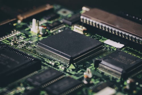
How Electronic Components Work Together on a PCB
Every resistor, capacitor, integrated circuit, connector, and protection device performs a specific function, but the real value of a PCB comes from how those components work together as a complete electrical system.
A reliable PCB distributes power, processes information, communicates with external devices, protects against electrical faults, and manages heat—all through carefully designed interactions between electronic components. Even the best components can perform poorly if they are improperly connected, poorly placed, or supported by an inadequate PCB layout.
Understanding how electronic components interact helps engineers design products that are electrically robust, easier to manufacture, and more reliable throughout their service life.
At AdvancedPCB, our fabrication and assembly teams evaluate not only individual component footprints, but also how complete systems are designed, manufactured, and inspected to ensure consistent performance from prototype through production.
Rather than thinking about individual components, engineers often organize designs into subsystems that work together.
Typical functional blocks include:
Voltage Regulation and Power Distribution
Most electronic products require multiple supply voltages.
For example, a single PCB may require:
Power regulation typically involves:
Good power distribution includes:
One of the smallest—but most important—components on a PCB is the decoupling capacitor.
As processors and integrated circuits switch millions or billions of times per second, they draw extremely fast bursts of current.
Nearby ceramic capacitors provide this instantaneous energy before current arrives through the larger power distribution network.
Without adequate decoupling:
Processors Coordinate the Entire System
The processor or microcontroller is the brain of most electronic systems.
It communicates with nearly every other functional block.
Typical processor connections include:
Without these supporting devices, even the most advanced processor cannot function reliably.
Memory Stores Information
Memory devices provide permanent or temporary storage for software and data.
Common memory types include:
Analog Circuits Prepare Real-World Signals
Many electronic products interact with the physical world.
Sensors convert temperature, pressure, motion, light, sound, or biological signals into electrical signals.
These signals often require conditioning before they reach the processor.
Analog circuits commonly include:
Communication Interfaces Connect Systems
Modern electronic products rarely operate alone.
Communication circuits allow PCBs to exchange information with other devices.
Common interfaces include:
Signal Integrity Keeps Data Reliable
At high frequencies, PCB traces no longer behave like simple wires.
Instead, they act as controlled transmission lines.
Signal integrity focuses on maintaining clean electrical signals as they travel across the PCB.
Engineers improve signal integrity through:
Grounding Is More Than Just "Ground"
Every electrical signal requires a return path.
Ground planes provide these return paths while minimizing electrical noise.
Effective grounding practices include:
Every electronic component generates heat.
Processors, power semiconductors, LEDs, regulators, and high-current resistors often produce significant thermal energy.
Good thermal management includes:

Figure 2. Cross-sectional illustration showing power flow, signal flow, return current paths, thermal vias, copper planes, and heat spreading through a multilayer PCB populated with processors, regulators, memory, and connectors.
Why PCB Layout Matters
The schematic defines how components should connect electrically.
The PCB layout determines whether those connections perform as intended.
Good PCB layout includes:
Manufacturing Quality Affects Electrical Performance
A well-designed PCB still depends on high-quality fabrication and assembly.
PCB manufacturing influences:
IPC Standards That Support Reliable PCB Design
Several IPC standards help engineers translate electronic component selections into reliable PCB assemblies.
These include:
From Components to Reliable Products
A successful PCB is more than a collection of quality components. Reliable products result from thoughtful system architecture, careful component placement, sound PCB layout, robust power distribution, effective thermal management, and manufacturing processes that consistently reproduce the engineer's design intent.
At AdvancedPCB, our engineering teams evaluate every design through a Design for Manufacturability (DFM) review before fabrication and assembly begin. We assess component spacing, thermal considerations, package compatibility, signal routing, and manufacturing risks to help customers move confidently from prototype to production.
By combining sound engineering practices with experienced PCB fabrication and assembly, manufacturers can transform individual electronic components into reliable electronic systems.
A PCB Is Built from Functional Blocks
Although every electronic product is different, most PCBs contain the same fundamental functional blocks.
Rather than thinking about individual components, engineers often organize designs into subsystems that work together.
Typical functional blocks include:
Figure 1. Functional block diagram of a PCB showing power input, protection, voltage regulation, processor, memory, sensors, communication interfaces, connectors, and output drivers connected by signal and power paths.
Power Input and Circuit Protection
Every electronic system begins with power.
Whether power comes from a battery, wall adapter, USB connection, or industrial power supply, it first enters the PCB through a connector or terminal block.
Before power reaches sensitive electronics, several protection components typically safeguard the system.
Common protection components include:
Voltage Regulation and Power Distribution
Most electronic products require multiple supply voltages.
For example, a single PCB may require:
Power regulation typically involves:
Good power distribution includes:
One of the smallest—but most important—components on a PCB is the decoupling capacitor.
As processors and integrated circuits switch millions or billions of times per second, they draw extremely fast bursts of current.
Nearby ceramic capacitors provide this instantaneous energy before current arrives through the larger power distribution network.
Without adequate decoupling:
Processors Coordinate the Entire System
The processor or microcontroller is the brain of most electronic systems.
It communicates with nearly every other functional block.
Typical processor connections include:
Without these supporting devices, even the most advanced processor cannot function reliably.
Memory Stores Information
Memory devices provide permanent or temporary storage for software and data.
Common memory types include:
Analog Circuits Prepare Real-World Signals
Many electronic products interact with the physical world.
Sensors convert temperature, pressure, motion, light, sound, or biological signals into electrical signals.
These signals often require conditioning before they reach the processor.
Analog circuits commonly include:
Communication Interfaces Connect Systems
Modern electronic products rarely operate alone.
Communication circuits allow PCBs to exchange information with other devices.
Common interfaces include:
Signal Integrity Keeps Data Reliable
At high frequencies, PCB traces no longer behave like simple wires.
Instead, they act as controlled transmission lines.
Signal integrity focuses on maintaining clean electrical signals as they travel across the PCB.
Engineers improve signal integrity through:
Grounding Is More Than Just "Ground"
Every electrical signal requires a return path.
Ground planes provide these return paths while minimizing electrical noise.
Effective grounding practices include:
Every electronic component generates heat.
Processors, power semiconductors, LEDs, regulators, and high-current resistors often produce significant thermal energy.
Good thermal management includes:

Figure 2. Cross-sectional illustration showing power flow, signal flow, return current paths, thermal vias, copper planes, and heat spreading through a multilayer PCB populated with processors, regulators, memory, and connectors.
Why PCB Layout Matters
The schematic defines how components should connect electrically.
The PCB layout determines whether those connections perform as intended.
Good PCB layout includes:
Manufacturing Quality Affects Electrical Performance
A well-designed PCB still depends on high-quality fabrication and assembly.
PCB manufacturing influences:
IPC Standards That Support Reliable PCB Design
Several IPC standards help engineers translate electronic component selections into reliable PCB assemblies.
These include:
From Components to Reliable Products
A successful PCB is more than a collection of quality components. Reliable products result from thoughtful system architecture, careful component placement, sound PCB layout, robust power distribution, effective thermal management, and manufacturing processes that consistently reproduce the engineer's design intent.
At AdvancedPCB, our engineering teams evaluate every design through a Design for Manufacturability (DFM) review before fabrication and assembly begin. We assess component spacing, thermal considerations, package compatibility, signal routing, and manufacturing risks to help customers move confidently from prototype to production.
By combining sound engineering practices with experienced PCB fabrication and assembly, manufacturers can transform individual electronic components into reliable electronic systems.
Every resistor, capacitor, integrated circuit, connector, and protection device performs a specific function, but the real value of a PCB comes from how those components work together as a complete electrical system.
A reliable PCB distributes power, processes information, communicates with external devices, protects against electrical faults, and manages heat—all through carefully designed interactions between electronic components. Even the best components can perform poorly if they are improperly connected, poorly placed, or supported by an inadequate PCB layout.
Understanding how electronic components interact helps engineers design products that are electrically robust, easier to manufacture, and more reliable throughout their service life.
At AdvancedPCB, our fabrication and assembly teams evaluate not only individual component footprints, but also how complete systems are designed, manufactured, and inspected to ensure consistent performance from prototype through production.
A PCB Is Built from Functional Blocks
Although every electronic product is different, most PCBs contain the same fundamental functional blocks.Rather than thinking about individual components, engineers often organize designs into subsystems that work together.
Typical functional blocks include:
- Power input and protection
- Voltage regulation
- Processing and control
- Memory
- Analog signal conditioning
- Communications
- Output drivers
- User interfaces
Each block depends on multiple electronic components working together to accomplish a specific task.
Figure 1. Functional block diagram of a PCB showing power input, protection, voltage regulation, processor, memory, sensors, communication interfaces, connectors, and output drivers connected by signal and power paths.'
Power Input and Circuit Protection
Every electronic system begins with power.
Whether power comes from a battery, wall adapter, USB connection, or industrial power supply, it first enters the PCB through a connector or terminal block.
Before power reaches sensitive electronics, several protection components typically safeguard the system.
Common protection components include:
- Fuses
- Resettable PTC devices
- TVS (Transient Voltage Suppression) diodes
- Reverse-polarity protection MOSFETs
- EMI filters
- Ferrite beads
- Electrostatic discharge (ESD)
- Voltage surges
- Reverse polarity
- Overcurrent conditions
- Conducted electrical noise
Voltage Regulation and Power Distribution
Most electronic products require multiple supply voltages.
For example, a single PCB may require:
- 12 V for motors
- 5 V for sensors
- 3.3 V for digital logic
- 1.2 V for processors
Power regulation typically involves:
- Switching regulators
- Linear regulators
- Inductors
- Capacitors
- MOSFETs
- Feedback resistors
Good power distribution includes:
- Continuous power planes
- Low-impedance ground planes
- Short power paths
- Wide copper traces for high current
- Proper decoupling
- Voltage droop
- Processor resets
- Excessive noise
- Electromagnetic interference (EMI)
- Reduced reliability
One of the smallest—but most important—components on a PCB is the decoupling capacitor.
As processors and integrated circuits switch millions or billions of times per second, they draw extremely fast bursts of current.
Nearby ceramic capacitors provide this instantaneous energy before current arrives through the larger power distribution network.
Without adequate decoupling:
- Digital noise increases.
- Voltage rails fluctuate.
- High-speed devices become unstable.
- Electromagnetic emissions increase.
Processors Coordinate the Entire System
The processor or microcontroller is the brain of most electronic systems.
It communicates with nearly every other functional block.
Typical processor connections include:
- Memory
- Sensors
- Power management
- Communication interfaces
- User inputs
- Displays
- Motor drivers
- Storage devices
Without these supporting devices, even the most advanced processor cannot function reliably.
Memory Stores Information
Memory devices provide permanent or temporary storage for software and data.
Common memory types include:
- Flash memory
- EEPROM
- SRAM
- DRAM
- Firmware
- Configuration settings
- Sensor data
- Operating parameters
- User information
Analog Circuits Prepare Real-World Signals
Many electronic products interact with the physical world.
Sensors convert temperature, pressure, motion, light, sound, or biological signals into electrical signals.
These signals often require conditioning before they reach the processor.
Analog circuits commonly include:
- Operational amplifiers
- Filters
- Voltage references
- Analog-to-digital converters (ADCs)
- Noise
- Grounding
- Trace routing
- Power supply cleanliness
Communication Interfaces Connect Systems
Modern electronic products rarely operate alone.
Communication circuits allow PCBs to exchange information with other devices.
Common interfaces include:
- USB
- Ethernet
- CAN
- SPI
- I²C
- UART
- Bluetooth®
- Wi-Fi
- Transceivers
- Oscillators
- Connectors
- Protection devices
- Termination resistors
- EMI filters
Signal Integrity Keeps Data Reliable
At high frequencies, PCB traces no longer behave like simple wires.
Instead, they act as controlled transmission lines.
Signal integrity focuses on maintaining clean electrical signals as they travel across the PCB.
Engineers improve signal integrity through:
- Controlled impedance routing
- Continuous reference planes
- Proper termination
- Differential pair routing
- Length matching
- Short return current paths
- DDR memory
- USB
- PCI Express
- HDMI
- Ethernet
- LVDS
Grounding Is More Than Just "Ground"
Every electrical signal requires a return path.
Ground planes provide these return paths while minimizing electrical noise.
Effective grounding practices include:
- Continuous ground planes
- Small current loops
- Proper connector grounding
- Separation of noisy switching circuits from sensitive analog circuits
- Careful management of return currents
- EMI failures
- Crosstalk
- Noise
- Unstable analog measurements
Every electronic component generates heat.
Processors, power semiconductors, LEDs, regulators, and high-current resistors often produce significant thermal energy.
Good thermal management includes:
- Copper pours
- Thermal vias
- Heat sinks
- Airflow
- Component spacing
- Proper package selection
Figure 2. Cross-sectional illustration showing power flow, signal flow, return current paths, thermal vias, copper planes, and heat spreading through a multilayer PCB populated with processors, regulators, memory, and connectors.
Why PCB Layout Matters
The schematic defines how components should connect electrically.
The PCB layout determines whether those connections perform as intended.
Good PCB layout includes:
- Proper component placement
- Short high-current paths
- Controlled impedance routing
- Effective grounding
- Adequate spacing
- Thermal management
- Manufacturable footprints
Manufacturing Quality Affects Electrical Performance
A well-designed PCB still depends on high-quality fabrication and assembly.
PCB manufacturing influences:
- Controlled impedance
- Copper thickness
- Via reliability
- Registration accuracy
- Surface finish
- Solder joint quality
- Component placement accuracy
- Solder paste volume
- Reflow consistency
- Polarity verification
- X-ray inspection
- Automated optical inspection (AOI)
IPC Standards That Support Reliable PCB Design
Several IPC standards help engineers translate electronic component selections into reliable PCB assemblies.
These include:
- IPC-2221 — Generic standard on printed board design.
- IPC-7351 — Surface-mount land pattern design.
- IPC-A-610 — Acceptability of electronic assemblies.
- IPC-6012 — Qualification and performance requirements for rigid printed boards.
From Components to Reliable Products
A successful PCB is more than a collection of quality components. Reliable products result from thoughtful system architecture, careful component placement, sound PCB layout, robust power distribution, effective thermal management, and manufacturing processes that consistently reproduce the engineer's design intent.
At AdvancedPCB, our engineering teams evaluate every design through a Design for Manufacturability (DFM) review before fabrication and assembly begin. We assess component spacing, thermal considerations, package compatibility, signal routing, and manufacturing risks to help customers move confidently from prototype to production.
By combining sound engineering practices with experienced PCB fabrication and assembly, manufacturers can transform individual electronic components into reliable electronic systems.
A PCB Is Built from Functional Blocks
Although every electronic product is different, most PCBs contain the same fundamental functional blocks.
Rather than thinking about individual components, engineers often organize designs into subsystems that work together.
Typical functional blocks include:
- Power input and protection
- Voltage regulation
- Processing and control
- Memory
- Analog signal conditioning
- Communications
- Output drivers
- User interfaces
Power Input and Circuit Protection
Every electronic system begins with power.
Whether power comes from a battery, wall adapter, USB connection, or industrial power supply, it first enters the PCB through a connector or terminal block.
Before power reaches sensitive electronics, several protection components typically safeguard the system.
Common protection components include:
- Fuses
- Resettable PTC devices
- TVS (Transient Voltage Suppression) diodes
- Reverse-polarity protection MOSFETs
- EMI filters
- Ferrite beads
- Electrostatic discharge (ESD)
- Voltage surges
- Reverse polarity
- Overcurrent conditions
- Conducted electrical noise
Voltage Regulation and Power Distribution
Most electronic products require multiple supply voltages.
For example, a single PCB may require:
- 12 V for motors
- 5 V for sensors
- 3.3 V for digital logic
- 1.2 V for processors
Power regulation typically involves:
- Switching regulators
- Linear regulators
- Inductors
- Capacitors
- MOSFETs
- Feedback resistors
Good power distribution includes:
- Continuous power planes
- Low-impedance ground planes
- Short power paths
- Wide copper traces for high current
- Proper decoupling
- Voltage droop
- Processor resets
- Excessive noise
- Electromagnetic interference (EMI)
- Reduced reliability
One of the smallest—but most important—components on a PCB is the decoupling capacitor.
As processors and integrated circuits switch millions or billions of times per second, they draw extremely fast bursts of current.
Nearby ceramic capacitors provide this instantaneous energy before current arrives through the larger power distribution network.
Without adequate decoupling:
- Digital noise increases.
- Voltage rails fluctuate.
- High-speed devices become unstable.
- Electromagnetic emissions increase.
Processors Coordinate the Entire System
The processor or microcontroller is the brain of most electronic systems.
It communicates with nearly every other functional block.
Typical processor connections include:
- Memory
- Sensors
- Power management
- Communication interfaces
- User inputs
- Displays
- Motor drivers
- Storage devices
Without these supporting devices, even the most advanced processor cannot function reliably.
Memory Stores Information
Memory devices provide permanent or temporary storage for software and data.
Common memory types include:
- Flash memory
- EEPROM
- SRAM
- DRAM
- Firmware
- Configuration settings
- Sensor data
- Operating parameters
- User information
Analog Circuits Prepare Real-World Signals
Many electronic products interact with the physical world.
Sensors convert temperature, pressure, motion, light, sound, or biological signals into electrical signals.
These signals often require conditioning before they reach the processor.
Analog circuits commonly include:
- Operational amplifiers
- Filters
- Voltage references
- Analog-to-digital converters (ADCs)
- Noise
- Grounding
- Trace routing
- Power supply cleanliness
Communication Interfaces Connect Systems
Modern electronic products rarely operate alone.
Communication circuits allow PCBs to exchange information with other devices.
Common interfaces include:
- USB
- Ethernet
- CAN
- SPI
- I²C
- UART
- Bluetooth®
- Wi-Fi
- Transceivers
- Oscillators
- Connectors
- Protection devices
- Termination resistors
- EMI filters
Signal Integrity Keeps Data Reliable
At high frequencies, PCB traces no longer behave like simple wires.
Instead, they act as controlled transmission lines.
Signal integrity focuses on maintaining clean electrical signals as they travel across the PCB.
Engineers improve signal integrity through:
- Controlled impedance routing
- Continuous reference planes
- Proper termination
- Differential pair routing
- Length matching
- Short return current paths
- DDR memory
- USB
- PCI Express
- HDMI
- Ethernet
- LVDS
Grounding Is More Than Just "Ground"
Every electrical signal requires a return path.
Ground planes provide these return paths while minimizing electrical noise.
Effective grounding practices include:
- Continuous ground planes
- Small current loops
- Proper connector grounding
- Separation of noisy switching circuits from sensitive analog circuits
- Careful management of return currents
- EMI failures
- Crosstalk
- Noise
- Unstable analog measurements
Every electronic component generates heat.
Processors, power semiconductors, LEDs, regulators, and high-current resistors often produce significant thermal energy.
Good thermal management includes:
- Copper pours
- Thermal vias
- Heat sinks
- Airflow
- Component spacing
- Proper package selection
Figure 2. Cross-sectional illustration showing power flow, signal flow, return current paths, thermal vias, copper planes, and heat spreading through a multilayer PCB populated with processors, regulators, memory, and connectors.
Why PCB Layout Matters
The schematic defines how components should connect electrically.
The PCB layout determines whether those connections perform as intended.
Good PCB layout includes:
- Proper component placement
- Short high-current paths
- Controlled impedance routing
- Effective grounding
- Adequate spacing
- Thermal management
- Manufacturable footprints
Manufacturing Quality Affects Electrical Performance
A well-designed PCB still depends on high-quality fabrication and assembly.
PCB manufacturing influences:
- Controlled impedance
- Copper thickness
- Via reliability
- Registration accuracy
- Surface finish
- Solder joint quality
- Component placement accuracy
- Solder paste volume
- Reflow consistency
- Polarity verification
- X-ray inspection
- Automated optical inspection (AOI)
IPC Standards That Support Reliable PCB Design
Several IPC standards help engineers translate electronic component selections into reliable PCB assemblies.
These include:
- IPC-2221 — Generic standard on printed board design.
- IPC-7351 — Surface-mount land pattern design.
- IPC-A-610 — Acceptability of electronic assemblies.
- IPC-6012 — Qualification and performance requirements for rigid printed boards.
From Components to Reliable Products
A successful PCB is more than a collection of quality components. Reliable products result from thoughtful system architecture, careful component placement, sound PCB layout, robust power distribution, effective thermal management, and manufacturing processes that consistently reproduce the engineer's design intent.
At AdvancedPCB, our engineering teams evaluate every design through a Design for Manufacturability (DFM) review before fabrication and assembly begin. We assess component spacing, thermal considerations, package compatibility, signal routing, and manufacturing risks to help customers move confidently from prototype to production.
By combining sound engineering practices with experienced PCB fabrication and assembly, manufacturers can transform individual electronic components into reliable electronic systems.
Browse
All Categories
Recent Posts
View Recent Posts