


7 PCB Design Priorities for Surgical Robotics
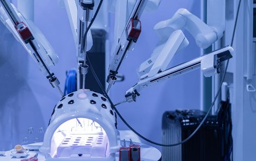
Surgical robotics combines precision motion, high-resolution imaging, responsive sensing, real-time processing, and safety-critical control inside increasingly compact systems. The printed circuit boards supporting those functions must handle dense routing, mixed-signal electronics, changing power demands, and demanding reliability expectations without introducing uncertainty into system performance.
For engineering teams, the challenge is not simply making the electronics smaller. It is integrating more capability into a limited space while preserving signal quality, power integrity, manufacturability, and consistency from the first prototype through production.

Before committing to an HDI construction, ask:
PCB design should account for voltage drop, transient loads, switching noise, return-current paths, and interactions between noisy and sensitive circuits. Useful practices include:
PCB-level thermal techniques may include:
In the United States, the FDA's Quality Management System Regulation became effective on February 2, 2026 and incorporates ISO 13485:2016 as the foundational quality-management framework for medical-device manufacturers. Finished-device regulatory responsibilities remain with the medical-device manufacturer, but PCB suppliers may need to support customer-defined documentation, process-control, change-control, and traceability requirements.
The PCB data package should clearly communicate:
Our teams can review stackups, materials, via structures, fine-feature requirements, controlled impedance, fabrication drawings, and manufacturing data before fabrication begins. That early collaboration helps engineering teams identify potential manufacturing concerns while there is still time to resolve them efficiently.
Explore AdvancedPCB's robotics capabilities
Submit files for a free DFM check
For engineering teams, the challenge is not simply making the electronics smaller. It is integrating more capability into a limited space while preserving signal quality, power integrity, manufacturability, and consistency from the first prototype through production.
Surgical Robotics PCB Design at a Glance
Successful surgical robotics PCB programs should address seven priorities early:- Define electrical, mechanical, and manufacturing requirements together.
- Protect sensitive imaging and sensor signals from electrical noise.
- Use HDI and fine-feature technologies intentionally, not simply to reduce board size.
- Plan power distribution and grounding for changing system loads.
- Establish a complete thermal path for compact electronics.
- Design for repeatable fabrication, documentation, and traceability.
- Validate the transition from prototype construction to production-ready manufacturing.
Why Surgical Robotics Creates Distinct PCB Requirements
A surgical robotics system may include cameras, encoders, force and position sensors, motor drives, processors, communications hardware, power conversion, and safety monitoring. These functions do not operate independently. They share physical space, power resources, grounding structures, and interconnects, which then create competing PCB demands such as:- High-speed digital signals must coexist with sensitive analog and sensor circuits.
- Motor drives and switching power supplies can introduce conducted and radiated noise.
- Compact packaging increases routing density and limits heat-spreading area.
- Mechanical constraints may require irregular board shapes, fine-pitch components, or rigid-flex construction.
- Frequent design revisions must remain documented and manufacturable.
- A validated design must be reproduced consistently as the program moves into production.
1. Define the Requirements Before Finalizing the Layout
Many expensive PCB changes begin with requirements that are incomplete, unclear, or introduced after routing was already underway. Before finalizing the board design, the engineering team should define elements including:- Finished board dimensions and component-height limits
- Expected layer count and finished thickness
- Material and surface-finish requirements
- Controlled-impedance targets and tolerances
- Current requirements and copper weights
- HDI, microvia, blind-via, buried-via, or via-in-pad needs
- Environmental, cleanliness, and reliability expectations
- Electrical testing, documentation, serialization, and traceability requirements
- Prototype, validation, and anticipated production volumes
2. Protect Imaging, Sensor, and Control Signals
Signal integrity is especially important when a system depends on accurate visual data, position feedback, force sensing, or responsive motion control. Noise or signal degradation can reduce margins, distort measurements, complicate troubleshooting, and create differences between prototype builds. Important PCB-level considerations include:- Defining controlled-impedance requirements before routing
- Maintaining continuous return paths beneath high-speed signals
- Avoiding unnecessary plane splits and reference-plane changes
- Separating sensitive analog and imaging circuits from motor-drive and switching nodes
- Controlling differential-pair geometry, spacing, and skew
- Placing decoupling components close to device power pins
- Minimizing stubs, discontinuities, and poorly planned layer transitions
- Reviewing connector launches and board-to-board interfaces
3. Use HDI to Increase Capability, Not Just Density
High-density interconnect technology can help surgical robotics teams fit more electronics into a smaller area. Microvias, fine lines and spaces, via-in-pad structures, sequential lamination, and smaller capture pads can free routing channels and reduce signal-path length. However, HDI is not automatically the best answer for every dense board. Each additional lamination cycle, stacked microvia structure, or filled-via requirement can affect manufacturing complexity, cost, lead time, and reliability evaluation.Before committing to an HDI construction, ask:
- Can component placement or pin assignment reduce routing congestion?
- Are blind or buried vias sufficient, or are microvias required?
- Can staggered microvias be used instead of stacked structures?
- Which components truly require via-in-pad?
- Does the design require filled and capped vias?
- Are the selected feature sizes appropriate for both prototype and production sources?
- Has the proposed structure been reviewed for manufacturability and reliability?
4. Design Power Distribution and Grounding as a System
Surgical robotic systems can combine processors, cameras, communications circuits, motors, actuators, and multiple power rails. The current demand may change as the system moves, processes imaging data, or activates different subsystems.PCB design should account for voltage drop, transient loads, switching noise, return-current paths, and interactions between noisy and sensitive circuits. Useful practices include:
- Estimating current by rail and operating mode
- Using planes and copper areas sized for the expected load
- Reviewing current density at neck-downs, vias, connectors, and layer transitions
- Providing adequate decoupling for high-speed devices and changing loads
- Separating high-current switching loops from sensitive sensing circuits
- Planning grounding around functional signal paths rather than relying on arbitrary plane divisions
- Evaluating power integrity together with signal integrity
5. Give Heat a Defined Path Out of the PCB
Compact electronics can concentrate heat around processors, power converters, motor-control devices, and other high-power components. Even when overall system power appears manageable, localized hot spots can affect component life, material behavior, sensor stability, and long-term reliability.PCB-level thermal techniques may include:
- Thermal via arrays beneath exposed pads
- Copper planes and internal heat-spreading structures
- Heavier copper in high-current or high-loss areas
- Via-in-pad structures where appropriate
- Direct coupling to heat spreaders, frames, or metal chassis features
- Materials selected for the actual temperature and reliability requirements
- Component placement that supports a continuous thermal path
6. Build Documentation and Traceability Into the Program
Surgical robotics development involves more than achieving electrical performance. The design and manufacturing information must remain controlled as the product evolves.In the United States, the FDA's Quality Management System Regulation became effective on February 2, 2026 and incorporates ISO 13485:2016 as the foundational quality-management framework for medical-device manufacturers. Finished-device regulatory responsibilities remain with the medical-device manufacturer, but PCB suppliers may need to support customer-defined documentation, process-control, change-control, and traceability requirements.
The PCB data package should clearly communicate:
- Part number and revision
- Approved stackup and materials
- Copper weights and finished thickness
- Controlled-impedance requirements
- Hole, slot, routing, and tolerance requirements
- Surface finish and solder-mask requirements
- Applicable workmanship or performance specifications
- Electrical-test requirements
- Serialization, certificates, reports, or other required records
- Approved deviations and engineering changes
7. Plan the Transition From Prototype to Production
A prototype proves that a concept can work. A production-ready design must also be repeatable, documented, testable, and practical to manufacture at the required volume. Before validation is complete, engineering teams should review:- Whether prototype materials and constructions will remain available
- Whether the selected tolerances are necessary and sustainable
- Whether special processes have been fully documented
- Whether alternate materials require approval and validation
- Whether electrical-test coverage matches the board's risk profile
- Whether fabrication notes, Gerbers, drill files, netlists, and drawings agree
- Whether manufacturing changes will trigger additional review or validation
Questions to Review With a Surgical Robotics PCB Manufacturer
Before releasing the next revision, ask:- Can the proposed stackup support the routing density and controlled-impedance requirements?
- Are the fine features, annular rings, and via structures appropriate for repeatable fabrication?
- Where are the highest signal-integrity and power-integrity risks?
- Does the design provide realistic paths for current and heat?
- Are all material and surface-finish requirements clearly documented?
- What testing, reporting, and traceability information should be specified on the fabrication drawing?
- Can the same construction support prototypes, validation builds, and anticipated production volumes?
How AdvancedPCB Supports Surgical Robotics Programs
AdvancedPCB supports robotics and medical-technology teams with quick-turn prototypes, engineering and DFM support, multilayer and HDI fabrication, controlled-impedance constructions, rigid-flex and flex capabilities, thermal-management technologies, electrical testing, and a path toward repeatable production.Our teams can review stackups, materials, via structures, fine-feature requirements, controlled impedance, fabrication drawings, and manufacturing data before fabrication begins. That early collaboration helps engineering teams identify potential manufacturing concerns while there is still time to resolve them efficiently.
Explore AdvancedPCB's robotics capabilities
Submit files for a free DFM check
Source Notes
- U.S. Food and Drug Administration, Quality Management System Regulation
- U.S. Food and Drug Administration, design and manufacturing control guidance
.png)
AdvancedPCB
FAQs for Surgical Robotic PCB Design Priorities
Does the PCB manufacturer determine medical-device compliance?
Is HDI always required for surgical robotics PCBs?
What PCB technologies are commonly used in surgical robotics?
When should a PCB manufacturer review the design?
Why is signal integrity important in surgical robotics?
Related Posts
.jpg?resizemode=force&maxsidesize=1226 "Large-Scale PCB Production")
Large Scale PCB Production
Reliable, Scalable Manufacturing Solutions
Large Scale PCB Production
Read More
RF Microwave PCB Design: Materials, Layout, and Manufacturing Best Practices
Learn RF microwave PCB design fundamentals including materials, impedance control, stackups, routing, testing, and manufacturing best practices.
RF Microwave PCB Design: Materials, Layout, and Manufacturing Best Practices
Read More
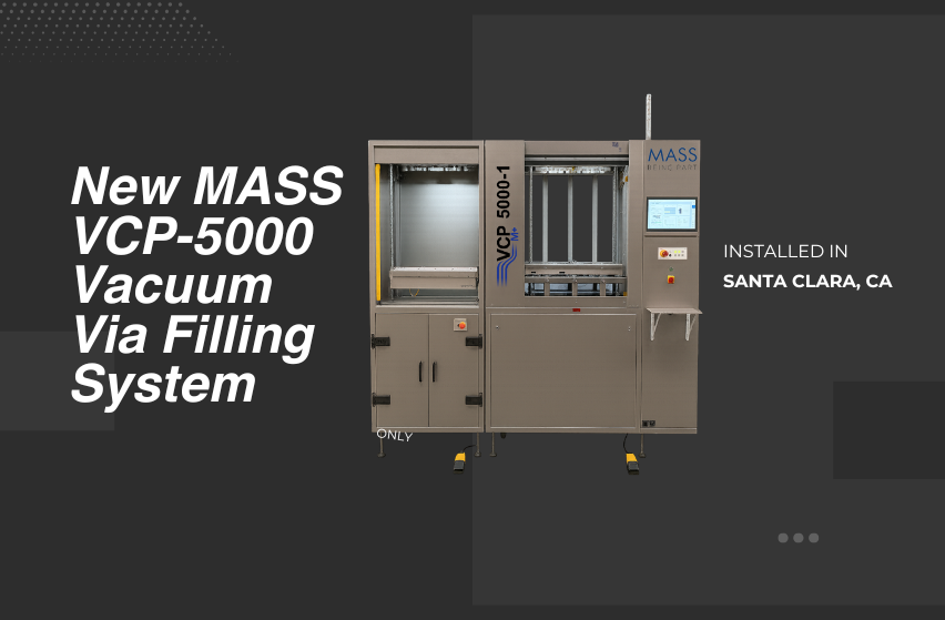
AdvancedPCB Expands HDI Capability in Silicon Valley with Advanced Vacuum Via Filling Technology
AdvancedPCB has installed a MASS VCP-5000 Vacuum Via Filling System at its Santa Clara facility, increasing capacity for advanced HDI PCBs.
AdvancedPCB Expands HDI Capability in Silicon Valley with Advanced Vacuum Via Filling Technology
Read More
Browse
All Categories
Recent Posts
View Recent Posts