PCB Tolerances: Standards, Practical Limits, and Design Guidance
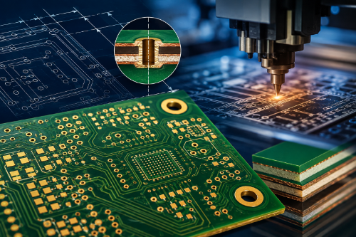
PCB tolerances define how much a finished printed circuit board can vary from the dimensions and specifications in the design. These allowable variations affect mechanical fit, electrical performance, assembly yield, controlled impedance, and long-term reliability.
PCB manufacturing is not a zero-variation process. Drilling, imaging, etching, plating, lamination, routing, and other processes introduce small dimensional changes. The goal is to establish tolerances that accommodate normal manufacturing variation while still meeting the functional requirements of the design.
Common PCB tolerances apply to board dimensions, finished thickness, hole size and position, conductor width and spacing, layer registration, solder mask registration, controlled impedance, and bow and twist. The appropriate tolerance depends on the board technology, materials, construction, manufacturing process, and applicable IPC requirements.
Understanding these variables early in the design process can help engineers avoid unnecessarily tight specifications, improve manufacturability, and control PCB cost and lead time.
What Are PCB Tolerances and Why Do They Matter?
PCB tolerances are the acceptable variations between the nominal values specified in a PCB design and the measurements of the finished board.
For example, if a finished hole is specified at 0.020 in. with a tolerance of ±0.003 in., an acceptable finished hole could measure between 0.017 and 0.023 in. The same principle applies to board dimensions, thickness, feature locations, controlled impedance, and other specifications.
There is no single tolerance that applies to every feature on a PCB. Each manufacturing process introduces different types and amounts of variation.
Common PCB tolerance categories include:
- Board outline and cutout dimensions
- Finished PCB thickness
- Finished hole diameter
- Hole position
- Layer-to-layer registration
- Conductor width and spacing
- Solder mask registration
- Controlled impedance
- Bow and twist
These tolerances can interact. Drill position and layer registration, for example, both influence the remaining annular ring around a plated through-hole. Board thickness can affect edge connectors and mechanical interfaces, while dimensional tolerances can determine whether mounting holes and connectors align correctly with an enclosure.
Tolerances also influence manufacturing cost. Specifying tighter tolerances than the design actually requires can demand tighter process controls, additional inspection, specialized processing, or lower manufacturing yields.
For this reason, designers should apply tight PCB tolerances only where they are functionally necessary.
PCB Tolerance Quick Reference Table
The values below are general starting points for common PCB designs, not universal manufacturing specifications. Actual PCB tolerances depend on the fabricator, materials, copper weight, board construction, feature geometry, manufacturing process, and applicable IPC requirements. Always confirm critical tolerances with your PCB manufacturer.| PCB Feature | Typical Starting Point | What Affects the Tolerance |
|---|---|---|
| Board outline | ±0.10 to ±0.20 mm (±0.004 to ±0.008 in.) | Routing process, board geometry, material, panelization |
| Finished PCB thickness | Approximately ±10% for many standard constructions | Stackup, laminate, prepreg, copper weight, plating, lamination |
| Plated through-hole diameter | ±0.076 to ±0.102 mm (±0.003 to ±0.004 in.) | Hole size, board thickness, aspect ratio, plating requirements |
| Trace/space | 0.10 mm / 0.10 mm (4/4 mil) is a common production capability | Copper thickness, etching, plating, layer type, manufacturing technology |
| Controlled impedance | ±10% is common; ±8% or ±5% may be available | Trace geometry, dielectric thickness, Dk, copper thickness, stackup |
| Solder mask registration | Fabricator-specific; confirm for fine-pitch designs | Imaging process, pad geometry, component pitch, mask technology |
| Layer registration | Fabricator- and technology-specific | Layer count, board thickness, materials, lamination, feature density |
| Bow and twist | ≤0.75% for boards using SMT; ≤1.5% for other boards* | Stackup symmetry, copper balance, material, board size, lamination |
*IPC-6012 generally specifies maximum bow and twist of 0.75% for boards using surface-mount components and 1.5% for other boards unless otherwise specified in the procurement documentation.
Important: These values should be used for general design guidance only. A manufacturer's standard production tolerance may differ, and advanced PCB technologies may support tighter limits. For critical dimensions or features, specify the required tolerance on the fabrication drawing and confirm manufacturability during DFM review.
PCB Board Outline and Dimensional Tolerances
Board outline tolerances determine how closely the finished PCB dimensions must match the dimensions specified in the fabrication data.
A typical routed PCB may have an outline tolerance in the range of approximately ±0.10 mm to ±0.20 mm (±0.004 to ±0.008 in.), although actual capabilities vary by manufacturer, board construction, routing process, and geometry.
Tighter tolerances may be possible for critical mechanical features, but they should be identified on the fabrication drawing and reviewed with the PCB manufacturer before production.
Dimensional tolerances become especially important when the PCB must interface with:
- Enclosures
- Card guides
- Connectors
- Mounting hardware
- Mechanical assemblies
- Mating PCBs
- Test fixtures
Cutouts and slots may also require separate tolerances from the overall board outline. Designers should identify dimensions that are functionally critical rather than applying an unnecessarily tight tolerance to every routed feature.
A clear datum scheme on the fabrication drawing can also help define how critical dimensions and feature locations should be measured.
PCB Thickness Tolerance
PCB thickness tolerance defines the allowable variation in the finished thickness of the circuit board.
A nominal 1.6 mm (0.062 in.) PCB, for example, will not necessarily measure exactly 1.6 mm after manufacturing. Final thickness is affected by the laminate construction, prepreg flow, copper thickness, plating, solder mask, and lamination process.
A finished PCB thickness tolerance of approximately ±10% is common for many commercial constructions, but this should not be treated as a universal manufacturing standard. Actual tolerances depend on the stackup, materials, board thickness, copper distribution, and PCB manufacturer's capabilities.
PCB thickness becomes particularly important for designs involving:
- Card-edge connectors
- Press-fit components
- Mechanical enclosures
- Board-to-board connections
- Controlled stack heights
- Gaskets or compression interfaces
If finished PCB thickness affects product fit or function, specify both the nominal thickness and required tolerance on the fabrication drawing.
For card-edge connectors in particular, designers should verify the acceptable PCB thickness range with both the connector manufacturer and PCB fabricator.
Trace Width and Spacing Tolerances
Trace width and spacing are affected by imaging, copper thickness, etching, and plating processes. As conductor features become smaller, normal process variation represents a larger percentage of the finished geometry.
Many PCB manufacturers can routinely produce 4 mil (0.10 mm) trace and space features on appropriate constructions. Features of 3 mil (0.076 mm) and below may require advanced processing, depending on copper thickness, layer type, board construction, and manufacturing technology.
Rather than assuming a universal trace-width tolerance, designers should review the manufacturer's published minimum conductor and spacing capabilities.
Copper weight is also important. Thicker copper generally requires wider traces and greater spacing because more copper must be removed during etching. A geometry that is straightforward with 0.5 oz or 1 oz copper may not be practical with substantially heavier copper.
For designs approaching a manufacturer's minimum capabilities, early DFM review is especially important.
Controlled Impedance Tolerances
Controlled impedance depends on more than trace width alone. Finished impedance is influenced by conductor geometry, copper thickness, dielectric thickness, dielectric properties, and the final PCB stackup.
A ±10% impedance tolerance is common for many controlled-impedance PCB designs. Some applications require tighter tolerances, such as ±8% or ±5%, but tighter requirements should be reviewed with the PCB manufacturer because they may affect materials, stackup, manufacturing controls, testing, cost, and lead time.
Designers should provide the manufacturer with:
- Target impedance
- Required impedance tolerance
- Signal type or structure
- Relevant controlled-impedance layers
- Stackup requirements or constraints
- Testing requirements
The PCB manufacturer may adjust production trace geometry to compensate for actual material properties and manufacturing processes while maintaining the required finished impedance.
When impedance is critical, the fabrication documentation should also define how compliance will be verified, such as through impedance test coupons.
Solder Mask and Silkscreen Tolerances
Solder mask must be registered accurately to the underlying copper features so that solderable areas remain exposed while adjacent conductors remain protected.
The required solder mask clearance depends on pad geometry, component pitch, mask process, and the PCB manufacturer's capabilities. While solder mask expansion values of a few mils have traditionally been common, modern processes such as laser direct imaging can support finer registration and more complex solder mask geometries.
For this reason, designers should avoid applying one universal solder mask expansion to every PCB design.
Fine-pitch components may require solder mask defined (SMD), non-solder mask defined (NSMD), or specialized mask geometries depending on the package and assembly process. BGA requirements should be coordinated with both the PCB fabricator and assembler.
Silkscreen or legend registration is generally less critical than copper or solder mask registration. However, legend should be kept away from exposed pads and other solderable surfaces so that ink does not interfere with assembly or inspection.
Finished Hole Size and Position Tolerances
PCB drawings should normally specify the required finished hole diameter, particularly for plated through-holes.
The PCB manufacturer selects a drill size that accounts for the copper plating and other processing required to achieve the specified finished diameter.
A common finished plated-hole tolerance may be approximately ±0.003 to ±0.004 in. (±0.076 to ±0.102 mm), but actual capability depends on hole diameter, board thickness, aspect ratio, plating requirements, and manufacturing process.
Hole position is another important consideration. Drilling and layer registration both contribute to the final relationship between the hole and its associated pads.
This becomes increasingly important for:
- Small vias
- High-aspect-ratio holes
- Dense multilayer designs
- Fine-pitch BGAs
- Press-fit holes
- Via-in-pad structures
Press-fit components deserve particular attention because both finished hole diameter and plating can affect the mechanical and electrical connection. Designers should follow the component manufacturer's recommended finished-hole requirements and coordinate them with the PCB fabricator.
Copper Plating and Annular Ring Requirements
Plated through-holes require sufficient copper on the hole wall to create a reliable electrical and mechanical connection between layers.
The required minimum copper plating thickness depends on the applicable PCB specification, performance class, hole type, and board construction. IPC requirements should therefore be applied according to the specific product and performance requirements rather than using a single plating value for every PCB.
Plating also affects finished hole size. The PCB manufacturer compensates for the copper deposited during processing when selecting the initial drill diameter.
Annular ring is the portion of the copper pad that remains around a finished hole. The final annular ring is affected by several manufacturing variables, including:
- Drill position
- Layer registration
- Pad diameter
- Hole diameter
- Imaging and etching variation
IPC acceptance requirements for annular ring vary by performance class and feature type. Designers should therefore size pads and holes to accommodate the expected manufacturing tolerance stack rather than relying on one universal minimum annular ring value.
For designs with small pads, dense via fields, or fine-pitch BGAs, DFM review can help determine whether the selected geometry provides sufficient manufacturing margin.
Layer-to-Layer Registration
Layer registration describes how accurately the copper features on individual PCB layers align with one another after imaging, lamination, and drilling.
Registration becomes more challenging as layer counts increase, boards become thicker, and feature sizes decrease. PCB materials also expand and contract during processing, particularly during lamination.
PCB manufacturers compensate for these effects through process controls, artwork scaling, tooling systems, imaging technology, and registration targets.
Registration is especially important for:
- High-layer-count PCBs
- HDI designs
- Fine-pitch BGAs
- Small vias
- Via-in-pad structures
- Sequential-lamination constructions
Rather than assuming a universal ±3 mil or ±5 mil registration tolerance, designers should evaluate the manufacturer's capabilities for the specific PCB technology being used.
Bow and Twist Tolerances
Bow and twist describe the flatness of a finished PCB.
Excessive bow or twist can interfere with component placement, solder paste printing, connector engagement, automated assembly, and mechanical installation.
IPC-6012 generally specifies a maximum bow and twist of 0.75% for boards that use surface-mount components and 1.5% for other boards, unless otherwise specified on the procurement documentation.
Some designs require tighter flatness limits. Fine-pitch BGAs, large boards, high-density assemblies, and certain mechanical interfaces may benefit from requirements below the general IPC limit.
PCB flatness is influenced by:
- Stackup symmetry
- Copper balance
- Material selection
- Lamination
- Board thickness
- Panel design
- Thermal processing
Designers should discuss unusually strict bow and twist requirements with the PCB manufacturer early because they can affect stackup and manufacturing strategy.
How Tight Can PCB Manufacturing Tolerances Be?
Advanced PCB manufacturing can achieve significantly tighter tolerances than standard production, but there is no single "tightest PCB tolerance."
Capability depends on the feature being controlled.
A manufacturer may be able to achieve very small traces and spaces while requiring different tolerances for routed dimensions, holes, registration, solder mask, or finished board thickness. HDI, microvias, via-in-pad, controlled impedance, and other advanced technologies may also require specialized manufacturing processes and inspection.
The important distinction is between manufacturing capability and production design rules.
A fabricator's absolute minimum capability represents what may be technically achievable under specific conditions. It should not automatically become the default design rule for every production board.
Designing with reasonable manufacturing margin generally improves yield, cost, and repeatability.
Applying PCB Tolerances During Design for Manufacturability
The best approach to PCB tolerances is to specify what the product actually requires—not simply the tightest number available.
During design for manufacturability (DFM), engineers should identify which dimensions and features are critical to electrical, mechanical, or assembly performance.
Tighter tolerances may be appropriate for:
- Controlled-impedance structures
- Press-fit holes
- Critical connector locations
- Card-edge thickness
- Fine-pitch features
- Critical mechanical cutouts
Noncritical dimensions can generally use the PCB manufacturer's standard tolerances.
Designers should also specify finished dimensions rather than manufacturing tool dimensions whenever possible. For example, specify the required finished plated-hole diameter rather than attempting to determine the fabrication drill size.
Early communication is especially important for complex stackups, HDI structures, microvias, via-in-pad, heavy copper, backdrilling, controlled impedance, and unusually tight mechanical requirements.
PCB Tolerance Design Checklist
Before releasing a PCB design for manufacturing:
- Confirm critical board outline and cutout tolerances.
- Establish clear dimensional datums where required.
- Define finished hole sizes and critical hole tolerances.
- Confirm press-fit hole requirements with the component manufacturer.
- Specify the nominal finished PCB thickness and tolerance when functionally important.
- Identify controlled-impedance targets and allowable tolerances.
- Define applicable materials, copper requirements, and IPC performance class.
- Confirm solder mask requirements for fine-pitch components.
- Specify any application-specific bow and twist requirements.
- Review advanced features with the PCB manufacturer before final release.
- Avoid applying unnecessarily tight tolerances to noncritical dimensions.
PCB Tolerances Should Be a Design Input
PCB tolerances should be considered during design, not after the PCB layout is complete.
Realistic tolerances give the manufacturer enough process margin to produce boards consistently while maintaining the electrical, mechanical, and assembly requirements of the finished product. Overly tight tolerances can increase cost and lead time without improving performance, while tolerances that are too loose can create fit, assembly, or reliability problems.
The best results come from identifying critical features early and aligning their requirements with the PCB manufacturer's demonstrated capabilities.
By treating PCB manufacturing tolerances—including board dimensions, hole sizes, registration, impedance, and PCB thickness tolerance—as part of the initial design strategy, engineers can improve manufacturability, increase production yield, and achieve more consistent results from prototype through production.
.png)
AdvancedPCB
FAQs for PCB Tolerances
Related Posts
Why Do PCBs Have an Even Number of Layers?