5 PCB Failures That Stop Robots
.jpg?resizemode=force&maxsidesize=500)
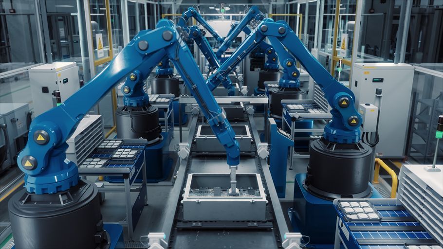
Robotic systems place unusual demands on printed circuit boards. Repeated motion, motor vibration, rapidly changing power loads, dense computing, multiple sensor interfaces, and long operating cycles can expose weaknesses that remain hidden during bench testing. A robot may perform well in a controlled demonstration but develop intermittent faults, positioning errors, thermal shutdowns, or unexpected downtime after repeated use in the field.
These failures are especially costly in industrial, warehouse, service, medical, and humanoid robots. A board-level issue can stop an entire work cell, interrupt a material-handling process, damage a payload, or create a safety risk when a robot operates near people.
Many of these problems can be prevented when PCB reliability, system architecture, and manufacturing requirements are addressed early. This article examines five common PCB failure modes in robotics, what causes them, and how design and manufacturing teams can reduce risk before production.
Failure 1: Solder Joint Fatigue from Vibration and Repeated Motion
What it looks like:
- Intermittent resets or communication errors during movement
- Encoder or sensor readings that become unstable at certain joint speeds
- Motor-control faults that are difficult to reproduce on the bench
- Connectors or heavy components loosening over time
- Assemblies that pass initial testing but fail after repeated duty cycles
 What’s actually happening:
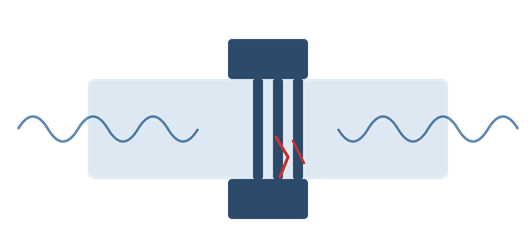
Motors, gearboxes, impact loads, abrupt stops, and repeated acceleration transmit mechanical stress into a robot's electronics. The resulting vibration is not always constant or predictable. Its frequency and amplitude can change with payload, speed, posture, floor conditions, tool use, and the wear state of mechanical components.
Over time, these loads can fatigue solder joints, particularly beneath BGAs and around large connectors, power components, shielded modules, tall capacitors, and heavy through-hole parts. Board flex can concentrate strain at component corners and mounting points until microcracks create intermittent electrical connections.
How to design against it:
- Define the real mechanical environment. Build vibration, shock, acceleration, and duty-cycle profiles from the robot's expected operating modes rather than relying only on generic test conditions.
- Mechanically support large components. Use appropriate staking, retention hardware, strain relief, or enclosure support for connectors, inductors, capacitors, and other heavy parts.
- Consider underfill for critical packages. Properly selected underfill can distribute stress beneath BGAs used for AI processing, motor control, perception, or system coordination. Its effect on reworkability and thermal behavior should also be evaluated.
- Control board stiffness and mounting. Board thickness, copper distribution, stiffeners, mounting locations, fastener support, and enclosure geometry all influence board deflection and resonance.
- Use high-reliability assembly processes with workmanship requirements appropriate for the application. AdvancedPCB supports a range of PCB certifications and industry standards for high-reliability applications.High-reliability programs may require IPC-A-610 and J-STD-001 Class 3 acceptance criteria, depending on the application and contractual requirements.
- Validate with representative testing. Combine vibration and mechanical cycling with powered functional monitoring so intermittent faults are captured while the robot is operating.
Humanoid robotics note: Bipedal walking, balance recovery, foot strike, falls, and frequent changes in posture can create highly variable loads. Electronics in the torso, limbs, hands, and feet may experience different vibration and shock profiles, so qualification should be performed at the subsystem level as well as on the complete robot.
Failure 2: Thermal Overload in Motor Drives, Power Distribution, and AI Compute
What it looks like:
- Motor drives shutting down under peak load
- Reduced torque or speed caused by thermal throttling
- Processor throttling during perception or planning tasks
- Brownouts when multiple actuators accelerate simultaneously
- Hot spots around MOSFETs, voltage regulators, processors, or connectors
- Laminate discoloration, delamination, or shortened component life
 What’s actually happening:
Robots combine high-current motor control with dense digital processing. Current demand can change rapidly as joints accelerate, lift a payload, recover balance, or resist an external force. At the same time, AI processors, cameras, networking devices, and power converters generate heat inside compact enclosures that may have limited airflow.
If conductor geometry, copper weight, thermal vias, planes, materials, or enclosure-level cooling are inadequate, heat accumulates faster than it can be removed. The system may operate normally during light tasks and fail only during sustained work or simultaneous peak loads.
How to design against it:
- Size conductors for the full load profile. Use IPC-2152 as a basis for conductor current and temperature-rise evaluation, while accounting for peak and continuous current, copper thickness, plane geometry, ambient temperature, airflow, and allowable temperature rise.
- Use heavier copper where required. Power distribution and motor-drive sections may need 2 oz or heavier copper. The appropriate construction depends on current, density, thermal limits, and fabrication constraints.
- Create effective thermal paths. Use properly designed copper areas and thermal via arrays beneath MOSFETs, regulators, processors, and exposed-pad packages to move heat into internal planes, heat spreaders, chassis structures, or cooling systems.
- Evaluate the laminate system. Review Tg, Td, Z-axis expansion, thermal conductivity, CAF resistance, and the expected temperature range rather than specifying material by a generic FR-4 label alone.
- Analyze transient conditions. Average current can conceal short, repeated thermal peaks. Model simultaneous actuator demand, regenerative events, stalled motors, worst-case payloads, and sustained compute workloads.
- Verify the complete thermal stack. PCB analysis should be correlated with the enclosure, interface materials, heat sinks, fans, liquid cooling, and nearby heat sources.
Humanoid robotics note: Humanoids distribute many high-torque actuators through a human-scale body with strict size and weight limits. The torso may also contain centralized computing and battery-management electronics. Designers must evaluate heat at individual joints and at the system level, including cases such as lifting, crouching, stair climbing, balance recovery, and sustained manipulation.
 Failure 3: EMI and Signal-Integrity Problems Disrupting Sensors and Real-Time Control
What it looks like:
- Encoder counts or force-sensor readings that jump unexpectedly
- Camera, lidar, radar, or depth-sensor dropouts
- CAN, EtherCAT, Ethernet, USB, or serial communication errors
- Unexplained motion-control instability during motor switching
- Wireless communication range that changes with robot activity
- False safety events or missed diagnostic messages
What’s actually happening:
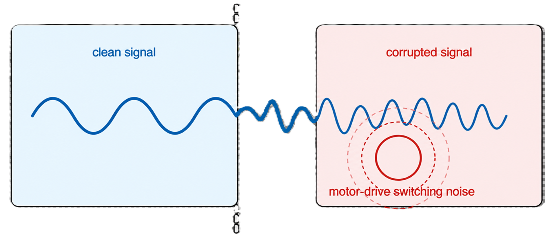
A robot places electrically noisy motor drives, switching regulators, high-current battery paths, fast digital interfaces, radios, and sensitive sensors in close proximity. Noise can couple through shared power networks, radiate from switching nodes or cable assemblies, and enter signal paths through discontinuous return planes or poor connector transitions.
In a real-time control system, a brief data error can have physical consequences. Corrupted position, force, torque, or inertial data can affect motion quality, while latency or packet loss can disrupt coordination between distributed controllers.
How to design against it:
- Separate noisy and sensitive functions. Partition motor-drive, power-conversion, RF, analog-sensor, and high-speed digital circuits while maintaining intentional return-current paths.
- Preserve reference-plane continuity. Avoid routing high-speed or noise-sensitive signals across plane splits, voids, or poorly planned layer transitions.
- Control impedance where required. Define impedance for Ethernet, USB, RF, camera, and other transmission-line interfaces, and include the requirements in the fabrication documentation.
- Reduce switching-loop area. Keep high di/dt paths compact, place decoupling close to devices, and control gate-drive and power-return geometry.
- Filter at domain boundaries. Apply suitable common-mode chokes, ferrites, filters, transient protection, and isolation where power or data crosses between subsystems.
- Plan cables and connectors as part of the signal path. Cable routing, shield termination, connector pinout, grounding, and transitions can negate otherwise good PCB layout.
- Perform pre-compliance testing early. Test representative assemblies with motors, radios, compute modules, sensors, and realistic cables operating together.
Humanoid robotics note: Humanoids often depend on tightly synchronized position, force, torque, tactile, vision, and inertial sensing to maintain balance and interact safely. Distributed joint controllers and long internal harness routes increase the number of possible coupling paths. Signal integrity and deterministic communication therefore become part of functional safety, not simply EMC compliance.
Failure 4: Flex-Circuit, Cable, and Connector Fatigue at Moving Joints
What it looks like: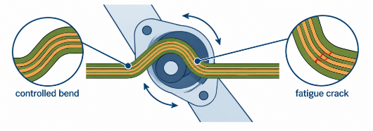
- A joint or end effector fails only at certain positions
- Sensor readings change as an arm, wrist, or gripper moves
- Intermittent open circuits after repeated cycles
- Cracked conductors near a rigid-to-flex transition
- Connector fretting, backed-out contacts, or damaged terminations
- A prototype works, but lifetime testing reveals early failures
What’s actually happening:
Robots route power and high-speed signals through moving axes. Every motion can bend, twist, or pull on flex circuits, wires, and connectors. If the bend radius, copper orientation, conductor stack, transition geometry, or strain relief is poorly designed, stress becomes concentrated in a small area. A design intended only to flex during installation may fail quickly when used in a dynamic application.
Electrical and mechanical design cannot be separated here. Routing that appears acceptable in CAD may behave differently after assembly because of torsion, connector placement, enclosure interference, tolerance stack-up, or an uncontrolled neutral bend axis.
How to design against it:
- Distinguish flex-to-install from dynamic flex. The appropriate flex or rigid-flex PCB construction depends on the expected number of cycles, bend radius, bend direction, torsion, temperature, and motion rate.
- Keep stress away from transitions. Avoid locating vias, component pads, sharp trace corners, or other stress concentrators near bend zones and rigid-to-flex interfaces.
- Use appropriate copper and layer construction. Rolled-annealed copper, fewer conductive layers in dynamic regions, staggered conductors, and adhesive choices may improve flex life when correctly applied.
- Route conductors perpendicular to the bend. Use smooth trace geometry and avoid abrupt width changes in repeatedly flexed areas.
- Provide controlled strain relief. Support cables and flex tails so movement is distributed over the intended bend zone rather than transferred into a solder joint or connector.
- Test the assembled motion path. Cycle the actual subsystem through worst-case travel, speed, load, and environmental conditions while monitoring electrical continuity and signal quality.
Humanoid robotics note: This issue becomes more severe in humanoids because of the number and range of articulated joints. Shoulders and wrists may require multi-axis motion; hands can include many small actuators and dense sensors; hips and ankles must carry high current while continuously changing orientation. Flex and harness design should be treated as a life-limited mechanical system with defined inspection and replacement criteria.
Failure 5: Design-to-Production Misalignment
What it looks like:
- Prototypes function, but production yield drops
- Performance changes between manufacturing lots
- Field reliability declines as volumes increase
- Substitute materials alter impedance, thermal behavior, or mechanical life
- Assembly variation affects sensors, connectors, or power electronics
- Root-cause investigations are slowed by incomplete traceability
 What’s actually happening:
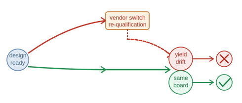
Robotics teams often iterate quickly. Early units may be hand assembled, reworked, or built with processes and materials that are difficult to reproduce at production scale. As the design moves from development to pilot builds and fleet deployment, changes in laminate, copper construction, via structures, soldering, cleaning, conformal coating, component sources, or test coverage can introduce variation.
For systems operating close to mechanical, thermal, or signal-integrity limits, small process changes can create large differences in reliability.
How to design against it:
- Engage manufacturing engineering before layout is complete. Review the stackup, materials, copper weights, via structures, impedance, panelization, tolerances, flex regions, and assembly constraints while changes are still inexpensive.
- Build a controlled path from prototype to production. If different facilities or suppliers are used, define which materials, processes, inspection methods, and acceptance criteria must remain equivalent.
- Qualify substitutions. Do not treat laminates, solder materials, connectors, or critical components as interchangeable without reviewing their electrical, thermal, and mechanical effects.
- Define inspection and test coverage. Use appropriate AOI, X-ray, electrical test, in-circuit or functional test, and powered subsystem testing based on the assembly and risk level.
- Require traceability. Material lots, fabrication batches, process data, inspection results, and assembly records help teams contain issues and identify root causes quickly.
- Use DFM review before fabrication. A thorough design for manufacturability review can identify stackup conflicts, inadequate clearances, difficult via structures, copper-balance issues, and documentation gaps before boards are built. Try our FreeDFM tool here >
Humanoid robotics note: Humanoid programs combine rapid design evolution with pressure to scale complex electromechanical systems. Revision control must extend beyond the central compute board to joint controllers, sensor boards, battery systems, hands, feet, and internal interconnects. A seemingly minor subsystem revision can affect balance, timing, thermal behavior, serviceability, or safety validation across the robot.
What Changes for Designing PCBs for Humanoid Robotics?
The five failure modes apply across industrial arms, autonomous mobile robots, warehouse systems, service robots, and research platforms. Humanoid robots, however, intensify several design requirements:
- More distributed electronics: Numerous joint, sensor, and actuator boards must communicate deterministically across the body.
- Higher interconnect-cycle demands: Repeated multi-axis movement makes flex circuits, cables, and connectors central lifetime-limiting components.
- Tighter power and thermal constraints: High-torque actuators and AI compute must fit within a mobile, human-scale package with limited cooling and battery capacity.
- Greater shock variability: Walking, foot strike, balance recovery, tool use, collisions, and falls create loads that differ across the body.
- Denser sensing: Vision, inertial, force, torque, position, touch, and safety sensors increase mixed-signal and EMI complexity.
- Operation near people: A momentary PCB or communication fault can become a motion-safety issue. Fault detection, redundancy, safe-state behavior, and diagnostic coverage must be addressed at the system architecture level.
- Serviceability at scale: Modular boards, controlled revisions, traceability, and accessible interconnects can reduce fleet downtime and simplify repairs.
These differences do not necessarily require a completely different PCB fabrication process. They do require earlier coordination among electrical, mechanical, controls, safety, thermal, and manufacturing teams.
Conclusion
Reliable robotic electronics require more than boards that pass initial electrical test. They must continue operating through repeated motion, vibration, transient current demand, heat, electrical noise, and thousands or millions of duty cycles.
Across all five failure modes, the pattern is consistent: risk is reduced when PCB construction, layout, materials, interconnects, assembly processes, and system-level testing are aligned early.
AdvancedPCB supports robotics programs from prototype through production with domestic PCB fabrication and assembly capabilities across six U.S. facilities. Our teams work with rigid, flex, and rigid-flex designs; controlled impedance; high-current and thermal requirements; advanced inspection; and high-reliability manufacturing requirements.
Before releasing your next robotics design, use our FreeDFM file check to identify potential manufacturability issues early, or contact our team to discuss your PCB requirements.
.png)
AdvancedPCB
Related Posts
Why Do PCBs Have an Even Number of Layers?

Heavy Copper PCBs for Automotive Electronics: Design Considerations