


Built for the Factory Floor
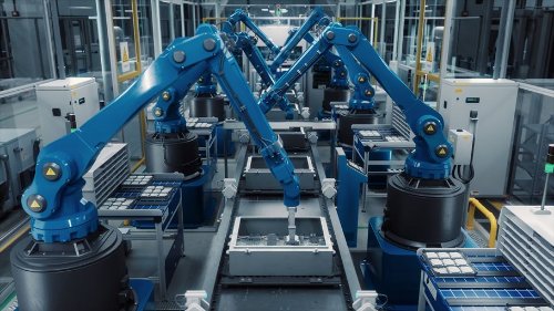
Industrial robots are expected to lift, weld, assemble, inspect, package, sort, and move materials for thousands of operating hours. Unlike electronics used in controlled office settings, robotic systems may face vibration, electrical noise, temperature changes, dust, moisture, chemicals, and repeated high-current loads.
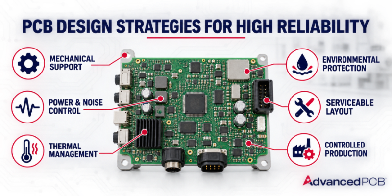
For PCB designers, reliability is not a single material choice or inspection step. It is the result of decisions made across the stackup, layout, materials, mechanical design, documentation, and manufacturing process. Addressing the operating environment early can reduce avoidable redesigns and create a more dependable path from prototype to production.
Before layout begins, define the expected temperature range, vibration and shock levels, duty cycle, contaminants, moisture exposure, cleaning processes, and electrical environment. These requirements guide material selection, board construction, component placement, protection methods, and test planning.
.png?lang=en-US&height=504&width=900 "WHERE-PCB-RELIABILITY-IS-CHALLENGED-IN-INDUSTRIAL-ROBOTICS-(1).png")
PCB mounting locations and fastener spacing should limit board flex. Heavy components may require additional mechanical support, and connectors should be positioned so cables do not transfer unnecessary force to the board. Component orientation, solder-joint geometry, and clearance around mounting hardware should be reviewed with the expected movement and service conditions in mind.
Flex and rigid-flex circuits can reduce connectors and cables in moving assemblies, but bend regions must be designed for the actual application. A circuit that bends once during installation has different requirements from one that moves repeatedly.
Functional zoning helps separate noisy power sections from sensitive control electronics. High-current paths should be short and direct, while sensitive signals should have continuous reference planes and predictable return paths. Filtering, grounding, shielding, decoupling, and connector placement should be planned as one system rather than addressed individually near the end of layout.
The PCB stackup should support required impedance, isolation, copper weight, and current capacity. Early collaboration with the PCB manufacturer can confirm whether the proposed materials and stackups will meet both electrical and fabrication requirements.
Thermal planning should identify the main heat sources and the complete path used to move heat away from them. Copper areas, thermal vias, heat spreaders, airflow, chassis connections, and component spacing may all contribute. Material properties should also be evaluated against the expected operating temperature and thermal-cycle profile.
Enclosures and seals provide the first line of defense. PCB cleanliness, spacing, surface finish, conformal coating, and material compatibility may provide additional protection. If conformal coating is required, the design should identify keepout areas, connectors, test points, and surfaces that must remain accessible.
Designers should preserve access to connectors, test points, and replaceable components. Clear labeling and serialization can help service teams identify assemblies and track revisions. Where practical, separating high-wear or application-specific functions from core processing electronics can also simplify maintenance and upgrades.
Fabrication data should clearly define the approved stackup, materials, copper weights, finished thickness, impedance requirements, surface finish, acceptance criteria, and testing. The design team and PCB manufacturer should resolve manufacturing questions before release and document any approved changes.
For PCB designers, reliability is not a single material choice or inspection step. It is the result of decisions made across the stackup, layout, materials, mechanical design, documentation, and manufacturing process. Addressing the operating environment early can reduce avoidable redesigns and create a more dependable path from prototype to production.
Start With the Actual Operating Environment
“Industrial” can describe very different conditions. A collaborative robot assembling electronics may operate in a relatively clean facility, while a welding robot, autonomous warehouse vehicle, or food-processing system may encounter contamination, shock, wide temperature changes, or frequent washdowns.Before layout begins, define the expected temperature range, vibration and shock levels, duty cycle, contaminants, moisture exposure, cleaning processes, and electrical environment. These requirements guide material selection, board construction, component placement, protection methods, and test planning.
Design for Vibration and Mechanical Stress
Industrial robots create repeated motion that can stress solder joints, connectors, cables, and heavy components. Mobile robots may also experience floor transitions, impacts, and continuous low-level vibration.PCB mounting locations and fastener spacing should limit board flex. Heavy components may require additional mechanical support, and connectors should be positioned so cables do not transfer unnecessary force to the board. Component orientation, solder-joint geometry, and clearance around mounting hardware should be reviewed with the expected movement and service conditions in mind.
Flex and rigid-flex circuits can reduce connectors and cables in moving assemblies, but bend regions must be designed for the actual application. A circuit that bends once during installation has different requirements from one that moves repeatedly.
Control Motor Noise and Power Disturbances
Motors, variable-frequency drives, switching power supplies, relays, and high-current conductors can produce electrical noise and voltage transients. At the same time, encoders, sensors, processors, safety circuits, and industrial communication links depend on stable power and clean signals.Functional zoning helps separate noisy power sections from sensitive control electronics. High-current paths should be short and direct, while sensitive signals should have continuous reference planes and predictable return paths. Filtering, grounding, shielding, decoupling, and connector placement should be planned as one system rather than addressed individually near the end of layout.
The PCB stackup should support required impedance, isolation, copper weight, and current capacity. Early collaboration with the PCB manufacturer can confirm whether the proposed materials and stackups will meet both electrical and fabrication requirements.
Account for Heat and Thermal Cycling
Continuous operation, power conversion, processors, and motor-control electronics can create localized heat. Repeated heating and cooling can place mechanical stress on materials, plated holes, solder joints, and component interfaces.Thermal planning should identify the main heat sources and the complete path used to move heat away from them. Copper areas, thermal vias, heat spreaders, airflow, chassis connections, and component spacing may all contribute. Material properties should also be evaluated against the expected operating temperature and thermal-cycle profile.
Protect Against Contamination
Dust, oil, moisture, metal particles, chemicals, and cleaning agents can affect insulation resistance, promote corrosion, or create unintended conductive paths. Protection should match the actual exposure rather than relying on a generic “harsh environment” assumption.Enclosures and seals provide the first line of defense. PCB cleanliness, spacing, surface finish, conformal coating, and material compatibility may provide additional protection. If conformal coating is required, the design should identify keepout areas, connectors, test points, and surfaces that must remain accessible.
Build for Serviceability
Industrial equipment often remains in service for years. A highly compact board may fit the enclosure but create difficulties during assembly, inspection, troubleshooting, or repair.Designers should preserve access to connectors, test points, and replaceable components. Clear labeling and serialization can help service teams identify assemblies and track revisions. Where practical, separating high-wear or application-specific functions from core processing electronics can also simplify maintenance and upgrades.
Preserve Reliability From Prototype to Production
A successful prototype does not automatically guarantee repeatable production. Material substitutions, stackup changes, component availability, incomplete drawings, or inconsistent test requirements can introduce variation after validation.Fabrication data should clearly define the approved stackup, materials, copper weights, finished thickness, impedance requirements, surface finish, acceptance criteria, and testing. The design team and PCB manufacturer should resolve manufacturing questions before release and document any approved changes.
Build Reliability Into the Design
Industrial robot reliability begins before the first board is fabricated. When the operating environment, mechanical loads, electrical noise, power demands, thermal conditions, contamination risks, and service requirements are addressed together, the PCB becomes a stronger foundation for long-term system performance.AdvancedPCB supports industrial robotics programs with engineering review, advanced PCB technologies, flex and rigid-flex capabilities, controlled impedance, heavy-copper options, quick-turn prototyping, and six U.S. manufacturing facilities. From early prototypes through production, our team helps customers identify manufacturability risks and build more repeatable PCB solutions.
To discuss an industrial robotics PCB project, visit AdvancedPCB's robotics page.
.png)
AdvancedPCB
FAQs for PCB Reliability in Robots
How can electrical noise affect an industrial robot?
How can PCB designs withstand vibration in industrial robots?
What makes an industrial robotics PCB a high-reliability PCB?
When should conformal coating be used on an industrial robotics PCB?
When should the PCB manufacturer become involved in an industrial robotics design?
Related Posts
Is Your Robotic PCB Design Ready for Manufacturing?
From Working Prototype to Production-Ready Industrial Robot PCB
Is Your Robotic PCB Design Ready for Manufacturing?
Read More

PCB Thermal Management for Robotics
How to design for Power, Motion, and Reliability
PCB Thermal Management for Robotics
Read More
.jpg?resizemode=force&maxsidesize=1226)
5 PCB Failures That Stop Robots
Learn the most common PCB failures in humanoid robotics.
5 PCB Failures That Stop Robots
Read More
Browse
All Categories
Recent Posts
View Recent Posts