PCBs for Humanoid Robotics

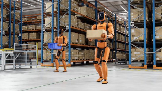
A humanoid robot packs dozens of actuators, a perception stack, onboard AI compute, and a battery system into a frame about the size of a person. Every one of those subsystems runs on circuit boards that must survive continuous motion, fit in tight volumes, and stay reliable through repeated impact. Below, we cover where PCBs are used in humanoid robots, the PCB technologies that fit each subsystem, key design considerations, and how we take programs from prototype to production.
6 U.S.-Based Facilities
IPC Class 3
ISO 9001:2015
ITAR Registered
Quick-turn to Volume
Where PCBs Live in a Humanoid
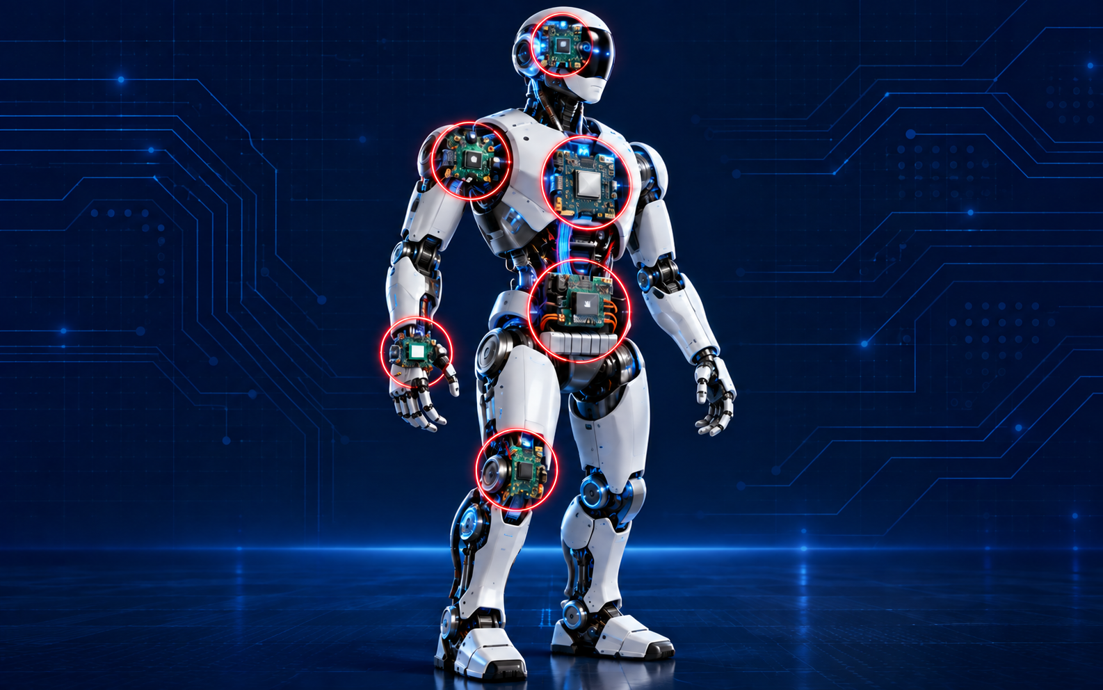
A humanoid robot is a distributed electronic system. Boards sit in every limb, joint, and sensor housing, and each location sets different requirements for the PCB.
- Joint Actuators and Motor Drivers. Compact driver and encoder boards mounted at each joint handle motor commutation, current sensing, and position feedback. They need high current capacity and thermal control in a small footprint.
- Hands and Grippers. Dexterous hands carry many actuators and tactile sensors in a very small volume. Flex and rigid-flex circuits route signals through fingers and wrists where rigid boards and cables cannot fit.
- Perception and Sensors. Cameras, depth sensors, IMUs, and force-torque sensors feed the control loop. These boards depend on low-noise layouts and controlled impedance for high-speed camera and data links.
- AI and Compute Modules. Onboard processors run perception, planning, and motion models in real time. Carrier boards for these modules use HDI, fine-pitch BGA breakout, and high-layer-count stackups.
- Battery and Power Distribution. Battery management and power distribution boards deliver current to many actuators at once. Heavy copper and careful thermal design keep voltage drop and heat under control.
- Communication Backbone. Motor controllers, sensors, and compute share data across the body over networks such as EtherCAT and CAN FD. These boards need clean signal integrity and isolation from nearby motor drive noise.
PCB Technologies for Humanoid Robots
Controlled Impedance
HDI and Microvia PCBs
Heavy Copper PCBs
Multilayer PCBs
Rigid-Flex and Flex PCBs
Thermal Management
Designing PCBs for Humanoid Robots
Humanoid platforms combine the constraints of consumer electronics, industrial motion control, and mobile power systems. Designs that account for manufacturing early move faster from prototype to fleet. Key considerations include:
- Dynamic flex life: bend radius, copper type, and coverlay selection for circuits that flex with every step and grip
- Size, weight, and power: reducing board area and mass without giving up current capacity
- Thermal density: planned heat paths for drivers and compute sealed inside limbs and torsos
- EMI and noise isolation: separating PWM motor currents from low-level sensor and encoder signals
- Shock and vibration: via structures, pad design, and component anchoring that hold up to repeated impact, including falls
AdvancedPCB engineers review stackups, flex design, and DFM with your team before release, so issues are caught before they affect your build schedule. Request a Free DFM Filecheck.
Certifications & Regulatory Compliance
Humanoid robots operate near people, so board-level reliability is a safety concern as well as a performance one. AdvancedPCB builds to documented, audited processes:
- ISO 9001:2015
Compliance with RoHS and REACH regulations
IPC Class 2 / Class 3 standards
ITAR registered for defense-related robotics programs
Comprehensive testing options: flying probe, fixture testing, X-ray inspections, ionic cleanliness assessments
Full traceability and revision control
From Prototype to Mass Production
Humanoid programs iterate quickly. Hardware revisions follow each round of gait, balance, and manipulation testing, and proven designs then need to scale to pilot fleets and production volumes.
- Quick-Turn Prototypes
Fast fabrication turns for rapid design iteration, with standard turns of 3-5 days. - Assembly and Validation
Prototype PCB assembly alongside fabrication reduces handoffs and gets functional hardware to your test lab sooner. - Scaled Production
Domestic production across six U.S. facilities, with global services available for high-volume programs.
Featured Articles
Engineering insights from the AdvancedPCB team on designing and building electronics for humanoid robots.
5 Common PCB Failures in Humanoid Robotics and How to Prevent Them
Solder joint fatigue, thermal overload, EMI, flex-circuit wear, and prototype-to-production drift are the failures that stop robots in the field. See what causes each one and the design and manufactur
Read the article