PCBs for Industrial Robotics

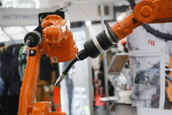
Industrial robots weld, paint, pick, pack, and assemble for shift after shift, often in environments full of vibration, heat, and electrical noise. The controllers, sensors, and safety systems behind that work all run on circuit boards that must hold up to continuous duty and stay in production for years.
Below, we cover where PCBs are used in industrial robots, the PCB technologies that fit each subsystem, key design considerations, and how we take programs from prototype to production.It is written by the AdvancedPCB team, drawing on PCB fabrication experience dating back to 1977 across six U.S. manufacturing facilities.
6 U.S.-Based Facilities
IPC Class 3
ISO 9001:2015
ITAR Registered
Quick-turn to Volume
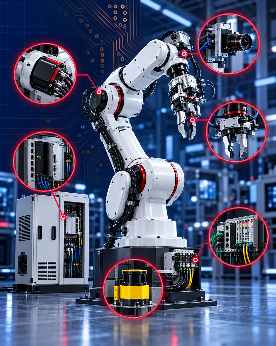
Where PCBs Live in an Industrial Robot
An industrial robot cell spans the arm, its controller, and the sensors and tooling around it, and each places different demands on the PCB.
- Servo Drives and Motor Control
Drive boards power the motors at each axis and close the position loop with encoder feedback. They need current-carrying capacity and thermal control for continuous operation. - Robot Controllers and Compute
The controller plans motion paths and coordinates every axis in real time. These boards use multilayer stackups, fine-pitch BGA breakout, and high-speed routing. - Machine Vision and Sensors
Cameras, encoders, and force-torque sensors guide picking, inspection, and assembly. Controlled impedance and low-noise layouts protect image and sensor data. - End-of-Arm Tooling and Grippers
Grippers, tool changers, and welding or dispensing heads carry electronics at the end of the arm. Flex and rigid-flex circuits can route signals through moving or limited-rotation wrist assemblies. - Safety Systems and Cobots
Safety controllers, torque sensing, and monitoring circuits let robots work near people. Redundant channels need clean isolation and consistent builds. - Industrial Networking and I/O
Robots exchange data with PLCs and the plant network over EtherCAT, PROFINET, and EtherNet/IP. These boards need signal integrity and protection from factory noise.
PCB Technologies for Industrial Robots
Heavy Copper PCBs
Thermal Management
Rigid-Flex and Flex PCBs
Controlled Impedance
HDI and Microvia PCBs
Long-Lifecycle Multilayer Builds
Designing PCBs for Industrial Robots
Industrial robots run harder and longer than most electronics. Designs that account for the operating environment and manufacturing early hold up better in the field. Key considerations include:
- Continuous-duty thermal design: heat paths designed for the robot’s defined continuous and peak operating loads, duty cycle, and surrounding temperature
- Current capacity: trace width, copper weight, and thermal design matched to continuous and peak current requirements
- Vibration and mechanical stress: via structures, pad design, and component anchoring for high-acceleration motion
- EMI on the factory floor: isolation from motor drives, VFDs, and welding equipment
- Environmental exposure: PCB surface finishes and assembly-level conformal coatings selected for exposure to dust, oil, coolant, moisture, and temperature changes
- Long product lifecycles: material choices and documentation that support years of consistent production
AdvancedPCB engineers review stackups, flex design, and DFM with your team before release, so issues are caught before they affect your build schedule. Request a Free DFM Filecheck.
Quality and Certifications
Unplanned downtime on a production line is expensive, so board-level reliability directly affects your customers’ output. AdvancedPCB builds to documented, audited processes:
- ISO 9001:2015
Compliance with RoHS and REACH regulations
PCB fabrication to IPC Class 2 or Class 3 acceptance criteria, as specified by the customer
ITAR registered for defense-related robotics programs
Comprehensive testing options: flying probe, fixture testing, X-ray inspections, ionic cleanliness assessments
Full traceability and revision control
From Prototype to Mass Production
Industrial robotics programs iterate through prototype and validation builds, then often stay in production for many years. The same boards need to be available and consistent long after launch.
- Quick-Turn Prototypes
Fast fabrication turns for rapid design iteration, with standard turns of 3-5 days. - Assembly and Verification Support
Prototype PCB assembly alongside fabrication reduces handoffs and gets functional hardware to your test lab sooner. - Scaled Production
Domestic production across six U.S. facilities, with global services available for mass production requirements.
Featured Articles
Engineering insights from the AdvancedPCB team on designing and manufacturing PCBs for industrial robotic systems.
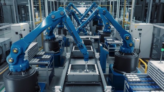
Built for the Factory Floor
Read the article